4607H-101-680LF Bourns Inc., 4607H-101-680LF Datasheet
4607H-101-680LF
Manufacturer Part Number
4607H-101-680LF
Description
Resistor Networks & Arrays 7pins 68ohms Bussed
Manufacturer
Bourns Inc.
Series
4600Hr
Datasheet
1.4607H-101-102LF.pdf
(2 pages)
Specifications of 4607H-101-680LF
Product Type
Networks
Circuit Type
Bussed
Number Of Resistors
6
Resistance
68 Ohms
Tolerance
2 %
Power Rating
0.3 Watt
Temperature Coefficient
+/- 100 PPM / C
Number Of Pins
7
Package / Case
SIP-7
Operating Temperature Range
- 55 C to + 125 C
Dimensions
8.89 mm W x 17.78 mm L x 2.49 mm H
Lead Spacing
2.54 mm
Termination Style
SIP
Body Material
Epoxy Resin
Lead Free Status / Rohs Status
Details


Resistance Range
Maximum Operating Voltage..........100 V
Temperature Coefficient of Resistance
TCR Tracking .........................50 ppm/°C
Resistor Tolerance ................See circuits
Insulation Resistance
Dielectric Withstanding Voltage
Operating Temperature
TESTS PER MIL-STD-202........ ∆R MAX.
Short Time Overload..................±0.25 %
Load Life ....................................±1.00 %
Moisture Resistance ..................±0.50 %
Resistance to Soldering Heat ....±0.25 %
Terminal Strength.......................±0.25 %
Thermal Shock...........................±0.25 %
Flammability .........Conforms to UL94V-0
Body Material........................Epoxy resin
Standard Packaging
Model
(46 = Conformal SIP)
Number of Pins
Physical Configuration
(H = Thick Film High Profile)
Electrical Configuration
• 101 = Bussed
• 102 = Isolated
• 104 = Dual Terminator
• AP1 = Bussed Ammo**
• AP2 = Isolated Ammo**
• AP4 = Dual Ammo**
Resistance Code
• First 2 digits are significant
• Third digit represents the
Resistance Tolerance
• Blank = ±2 % (see “Resistance Tolerance”
• F = ±1 % (100 ohms - 5 megohms)
Terminations
• All electrical configurations EXCEPT 104 & AP4:
• ONLY electrical configurations 104 & AP4:
Consult factory for other available options.
**Available for packages with 10 pins or less.
Product Characteristics
Environmental Characteristics
Physical Characteristics
How To Order
number of zeros to follow.
on next page for resistance range)
50 Ω to 2.2 MΩ................±100 ppm/°C
below 50 Ω ......................±250 ppm/°C
above 2.2 MΩ..................±250 ppm/°C
......................10 ohms to 10 megohms
.............................................200 VRMS
....................Bulk, Ammo-pak available
..................10,000 megohms minimum
.................................-55 °C to +125 °C
LF = Sn/Ag/Cu-plated (RoHS compliant)
L = Sn/Ag/Cu-plated (RoHS compliant)
46 06 H - 101 - 222 __ LF
maximum; equal values
Features
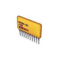
4600H Series - Thick Film Conformal SIPs
Represents total content. Layout may vary.
RC = ohmic value, 3-digit resistance code.
Pkg.
4604H
4605H
4606H
4607H
4608H
4609H
Typical Part Marking
Package Power Temp. Derating Curve
Package Power Ratings (Watts)
Part Number
4606H-101-RC
4608H-102-RC
4610H-104-RC/RC
3.50
3.00
2.50
2.00
1.50
1.00
RoHS compliant*
High profile offers increased power
handling
Wide assortment of pin packages
enhances design flexibility
Ammo-pak packaging available
.50
NUMBER OF PINS
0
4614H
4612H
4610H
4606H
4604H
4608H
Temperature
PIN ONE
INDICATOR
Ambient
25
70
0.80
1.00
1.20
1.40
1.60
1.80
AMBIENT TEMPERATURE ( C )
°
C
6H-2-222
YYWW
MANUFACTURER'S
TRADEMARK
Pkg.
4610H
4611H
4612H
4613H
4614H
CIRCUIT
70
Part Number
6H-1-RC
8H-2-RC
10H-4-RC/RC
RESISTANCE
CODE
DATE CODE
Temperature
Customers should verify actual device performance in their specific applications.
Ambient
70
2.00
2.20
2.40
2.60
2.80
°
°
125
C
*RoHS Directive 2002/95/EC Jan 27 2003 including Annex
Maximum package length is equal to 2.54mm (.100") times the
number of pins, less .005mm (.002").
Governing dimensions are in metric. Dimensions in parentheses
are inches and are approximate.
*Terminal centerline to centerline measurements made at point of
emergence of the lead from the body.
For Standard Values Used in Capacitors,
Inductors, and Resistors,
Product Dimensions
BOTH ENDS
Recommended for rosin flux and solvent
clean or no clean flux processes
Marking on contrasting background for
permanent identification
Specifications are subject to change without notice.
(.020 ± .002)
MAX.
.508 ± .050
(.100 ± .003*)
(.010 ± .002)
NON-ACCUM.
.254 ± .050
(.098)
2.54 ± .07
2.49
(.049)
PIN #1
1.24
TYP.
REF.
MAX.
TYP.
TYP.
MAXIMUM
A
Count
Pin
10
11
12
13
14
4
5
6
7
8
9
(.135 +.015/ -.020)
3.43 +.38/ -.508
click
(.350)
8.89
mm (Inches)
27.89 (1.098)
30.43 (1.198)
32.97 (1.298)
35.51 (1.398)
A Maximum
10.11 (.398)
12.65 (.498)
15.19 (.598)
17.73 (.698)
20.27 (.798)
22.81 (.898)
25.35 (.998)
here.
MAX.
Related parts for 4607H-101-680LF
Image
Part Number
Description
Manufacturer
Datasheet
Request
R

Part Number:
Description:
Resistor Networks & Arrays 7pins 2.7Kohms Bussed
Manufacturer:
Bourns Inc.
Datasheet:
Part Number:
Description:
Resistor Networks & Arrays 7pins 330Kohms Bussed
Manufacturer:
Bourns Inc.
Datasheet:
Part Number:
Description:
Resistor Networks & Arrays 7pins 1.5Kohms Bussed
Manufacturer:
Bourns Inc.
Datasheet:
Part Number:
Description:
Resistor Networks & Arrays 7pins 270Kohms Bussed
Manufacturer:
Bourns Inc.
Datasheet:
Part Number:
Description:
Resistor Networks & Arrays 7pins 18Kohms Bussed
Manufacturer:
Bourns Inc.
Datasheet:
Part Number:
Description:
Resistor Networks & Arrays 7pins 47Kohms Bussed
Manufacturer:
Bourns Inc.
Datasheet:
Part Number:
Description:
Resistor Networks & Arrays 7pins 180ohms Bussed
Manufacturer:
Bourns Inc.
Datasheet:
Part Number:
Description:
Resistor Networks & Arrays 7pins 2Kohms Bussed
Manufacturer:
Bourns Inc.
Datasheet:
Part Number:
Description:
Resistor Networks & Arrays 7pins 150ohms Bussed
Manufacturer:
Bourns Inc.
Datasheet:
Part Number:
Description:
Resistor Networks & Arrays 7pins 680Kohms Bussed
Manufacturer:
Bourns Inc.
Datasheet:

Part Number:
Description:
Manufacturer:
Bourns, Inc.
Datasheet:
Part Number:
Description:
11mm Potentiometer
Manufacturer:
Bourns, Inc.
Datasheet:
4607H-101-680LF Summary of contents
Page 1
... C Pkg 4604H 0.80 4610H 2.00 4605H 1.00 4611H 2.20 4606H 1.20 4612H 2.40 4607H 1.40 4613H 2.60 4608H 1.60 4614H 2.80 4609H 1.80 Typical Part Marking Represents total content. Layout may vary. Part Number Part Number 4606H-101-RC 6H-1-RC 4608H-102-RC 8H-2-RC ...
Page 2
... The 4608H-104 (shown above pin configuration and terminates 6 lines. Pins 1 and 8 are common for ground and power, respectively. Twelve thick-film resistors are paired in series between the common lines (pins 1 and 8). Resistance Tolerance Below 100 ohms .......................±2 ohms 100 ohms to 5 megohms ..............±2 %* Above 5 megohms .........................± ...