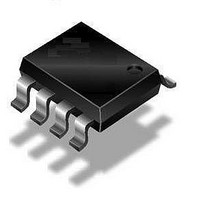
QT115A-ISG Atmel, QT115A-ISG Datasheet - Page 3

QT115A-ISG
Manufacturer Part Number
QT115A-ISG
Description
IC TOUCH SENSOR PROX 8SOIC
Manufacturer
Atmel
Datasheet
1.AT42QT1040-MMH.pdf
(72 pages)
Specifications of QT115A-ISG
Input Type
*
Output Type
*
Interface
*
Current - Supply
*
Mounting Type
Surface Mount
Operating Supply Voltage
3 V to 5 V
Maximum Operating Temperature
+ 85 C
Mounting Style
SMD/SMT
Package / Case
SO-8
Minimum Operating Temperature
- 40 C
Lead Free Status / RoHS Status
Lead free / RoHS Compliant
Package / Case
-
Lead Free Status / Rohs Status
Details
Touch Sensors Design Guide
Table of Contents
Section 1
Introduction To Sensor Design................................................................................... 1-1
Section 2
General Advice........................................................................................................... 2-1
Section 3
Self-capacitance Zero-dimensional Sensors.............................................................. 3-1
1.1
1.2
1.3
1.4
2.1
2.2
2.3
2.4
2.5
3.1
3.2
3.3
Introduction ........................................................................................................................ 1-1
Self-capacitance and Mutual-capacitance Type Sensors .................................................. 1-1
Dimension Groups ............................................................................................................. 1-2
Some Important Theory ..................................................................................................... 1-2
Charge Transfer................................................................................................................. 2-1
Components....................................................................................................................... 2-3
Materials ............................................................................................................................ 2-4
Nearby LEDs...................................................................................................................... 2-7
Electrostatic Discharge Protection ..................................................................................... 2-8
Introduction ........................................................................................................................ 3-1
Planar Construction ........................................................................................................... 3-1
Non-planar Construction .................................................................................................... 3-7
2.2.1
2.2.2
2.2.3
2.2.4
2.3.1
2.3.2
2.3.3
2.3.4
3.2.1
3.2.2
3.2.3
3.2.4
3.2.5
3.2.6
3.2.7
3.3.1
Cs Capacitor ........................................................................................................ 2-3
Series Resistors................................................................................................... 2-3
Voltage Regulator ................................................................................................ 2-3
Component Placement ........................................................................................ 2-3
Substrates ........................................................................................................... 2-4
Electrode and Interconnection Materials ............................................................. 2-4
Front Panel Materials........................................................................................... 2-5
PCB to Panel Bonding ......................................................................................... 2-6
Introduction .......................................................................................................... 3-1
Electrode Shapes ................................................................................................ 3-2
Ground Loading ................................................................................................... 3-3
Interconnection .................................................................................................... 3-4
Illumination Effects............................................................................................... 3-5
Floating Conductive Items ................................................................................... 3-6
Conductive Paints................................................................................................ 3-7
Printed Electrode Method .................................................................................... 3-8
10620D–AT42–04/09
iii


