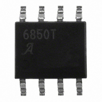
A6850KLTR-T Allegro Microsystems Inc, A6850KLTR-T Datasheet - Page 9

A6850KLTR-T
Manufacturer Part Number
A6850KLTR-T
Description
IC SWITCH INTERFACE 2CHAN 8-SOIC
Manufacturer
Allegro Microsystems Inc
Type
Hall Effect Switchr
Datasheet
1.A6850KLTR-T.pdf
(12 pages)
Specifications of A6850KLTR-T
Input Type
Voltage
Output Type
Voltage
Interface
2-Wire Serial
Current - Supply
5mA
Mounting Type
Surface Mount
Package / Case
8-SOIC (3.9mm Width)
Interface Applications
Microprocessors, 2 Wire Hall Effect Sensor IC
Supply Voltage Range
4.75V To 26.5V
Power Dissipation Pd
52mW
Operating Temperature Range
-40°C To +125°C
Lead Free Status / RoHS Status
Lead free / RoHS Compliant
Other names
620-1185-2
Available stocks
Company
Part Number
Manufacturer
Quantity
Price
Company:
Part Number:
A6850KLTR-T
Manufacturer:
ADI
Quantity:
1 131
A6850
Mechanical Switch Interfacing
The A6850 can be used as an interface between mechanical
switches, set in a switch-to-ground configuration, and a low
voltage microprocessor. A series resistor must be placed in
the circuit to limit current when the mechanical switch is
closed, in order to prevent excessive power dissipation in the
A6850.
For example, to calculate the power dissipation in the A6850
driving two mechanical switches with 1 kΩ series resistors,
with V
the outputs is set to the maximum value, I
45 mA.
When the mechanical switch is closed without a series resis-
tor, the A6850 will be at the current limit. The full 12 V of the
power supply will drop across the A6850 at 45mA The power
dissipation for one mechanical switch closed would be:
Figure 6. Typical Application with Mechanical Switches
P
IN
D1
= 12 V, assume that the current limit for each of
= V
= 12 V × 45 mA
= 540 mW
Drop1
V
CC
× I
OUTPUT1
Controller
VIN
Digital Output
Digital Output
Input1
Input2
RSENSE1
OUTPUTM
V
CC
V
BAT
or
(max) =
(6)
RSENSE2
1
3
2
4
1 µF
Dual Channel Switch Interface IC
ENABLE1
ENABLE2
SENSE1
SENSE2
A series resistor included in the circuit reduces power dis-
sipation in the OUTPUTx section of the A6850.
The current is then limited to:
I
The power dissipation in the A6850 from this switch is much
lower:
OUTPUT1
V
Drop1
P
D1
GROUND
A6850
VIN
= 12 V / 1035 Ω
= 11.59 mA
= 35 × I
= 405.7 mV
= V
= 0.4057 V × 11.3 mA
= 4.58 mW
= V
7
5
IN
Drop1
OUTPUT2
OUTPUT1
/ (35 + R
OUTPUT1
× I
OUTPUT1
SERIES
8
6
115 Northeast Cutoff
1.508.853.5000; www.allegromicro.com
Allegro MicroSystems, Inc.
Worcester, Massachusetts 01615-0036 U.S.A.
)
R
R
Wiring Harness
SERIES
SERIES
(7)
(8)
(9)
9


