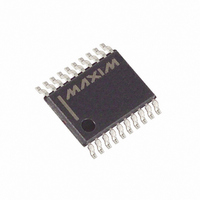
DS4550E+ Maxim Integrated Products, DS4550E+ Datasheet - Page 4

DS4550E+
Manufacturer Part Number
DS4550E+
Description
IC I/O EXPANDER I2C 9B 20TSSOP
Manufacturer
Maxim Integrated Products
Datasheet
1.DS4550ETR.pdf
(18 pages)
Specifications of DS4550E+
Interface
I²C
Number Of I /o
9
Interrupt Output
No
Frequency - Clock
400kHz
Voltage - Supply
2.7 V ~ 5.5 V
Operating Temperature
-40°C ~ 85°C
Mounting Type
Surface Mount
Package / Case
20-TSSOP
Includes
EEPROM, JTAG
Lead Free Status / RoHS Status
Lead free / RoHS Compliant
I
Expander Plus Memory
NONVOLATILE MEMORY CHARACTERISTICS
(V
Figure
4
Note 1: All voltages referenced to ground.
Note 2: I
Note 3: Guaranteed by design.
Note 4: Timing shown is for fast-mode (400kHz) operation. This device is also backward-compatible with I
Note 5: After this period, the first clock pulse is generated.
Note 6: C
Note 7: EEPROM write time applies to all the EEPROM memory and SRAM-shadowed EEPROM memory when SEE = 0. The
Note 8: TCK can be stopped either high or low.
Note 9: EEPROM write begins immediately after the UPDATE-DR state that latches the data to be written. The EEPROM cannot be
EEPROM Writes
2
CC
C and JTAG Nonvolatile 9-Bit I/O
_____________________________________________________________________
= +2.7V to +5.5V, unless otherwise noted.)
TDI, TMS
1. JTAG Timing Diagram
TCK
TDO
EEPROM write time begins after a stop condition occurs.
accessed until the EEPROM write has completed. However, the remainder of the JTAG functionality is active and accessi-
ble during the EEPROM write.
STBY
PARAMETER
B
total capacitance of one bus line in picofarads.
is specified with SDA = SCL = TMS = TDI = V
t
t
6
7
SYMBOL
t
2
+70°C (Note 3)
t
4
CC
t
1
, outputs floating, and inputs connected to V
CONDITIONS
t
5
t
3
50,000
MIN
2
TYP
C standard mode timing.
CC
or GND.
MAX
UNITS


