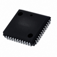
IMS82C55AZ Intersil, IMS82C55AZ Datasheet - Page 6

IMS82C55AZ
Manufacturer Part Number
IMS82C55AZ
Description
IC I/O EXPANDER 24B 44PLCC
Manufacturer
Intersil
Datasheet
1.CMS82C55AZ.pdf
(26 pages)
Specifications of IMS82C55AZ
Interface
Programmable
Number Of I /o
24
Interrupt Output
No
Voltage - Supply
4.5 V ~ 5.5 V
Operating Temperature
-40°C ~ 85°C
Mounting Type
Surface Mount
Package / Case
44-PLCC
Lead Free Status / RoHS Status
Lead free / RoHS Compliant
Frequency - Clock
-
Available stocks
Company
Part Number
Manufacturer
Quantity
Price
Interrupt Control Functions
When the 82C55A is programmed to operate in mode 1 or
mode 2, control signals are provided that can be used as
interrupt request inputs to the CPU. The interrupt request
signals, generated from port C, can be inhibited or enabled
by setting or resetting the associated INTE flip-flop, using
the bit set/reset function of port C.
This function allows the programmer to enable or disable a
CPU interrupt by a specific I/O device without affecting any
other device in the interrupt structure.
INTE Flip-Flop Definition
(BIT-SET)-INTE is SET - Interrupt Enable
(BIT-RESET)-INTE is Reset - Interrupt Disable
NOTE: All Mask flip-flops are automatically reset during mode
selection and device Reset.
Operating Modes
Mode 0 (Basic Input/Output). This functional configuration
provides simple input and output operations for each of the
Mode 0 (Basic Input)
D7 D6 D5 D4 D3 D2 D1 D0
X
DON’T
CARE
CONTROL WORD
CS, A1, A0
X
INPUT
FIGURE 5. BIT SET/RESET FORMAT
D7-D0
X
RD
6
BIT SET/RESET
1 = SET
0 = RESET
BIT SELECT
BIT SET/RESET FLAG
0 = ACTIVE
0
0 1 0 1 0 1 0 1
0 0 1 1 0 0 1 1
0 0 0 0 1 1 1 1
MS82C55A, MQ82C55A, MP82C55A
1 2 3 4 5 6 7
tAR
tIR
B0
B1
B2
tRD
tRR
three ports. No handshaking is required, data is simply
written to or read from a specific port.
Mode 0 Basic Functional Definitions:
• Two 8-bit ports and two 4-bit ports
• Any Port can be input or output
• Outputs are latched
• Inputs are not latched
• 16 different Input/Output configurations possible
D4
0
0
0
0
0
0
0
0
1
1
1
1
1
1
1
1
A
D3
0
0
0
0
1
1
1
1
0
0
0
0
1
1
1
1
D1
0
0
1
1
0
0
1
1
0
0
1
1
0
0
1
1
tHR
B
tRA
MODE 0 PORT DEFINITION
D0
0
1
0
1
0
1
0
1
0
1
0
1
0
1
0
1
tDF
PORT A
Output
Output
Output
Output
Output
Output
Output
Output
Input
Input
Input
Input
Input
Input
Input
Input
GROUP A
PORT C
(Upper)
Output
Output
Output
Output
Output
Output
Output
Output
Input
Input
Input
Input
Input
Input
Input
Input
10
12
13
14
15
11
#
0
1
2
3
4
5
6
7
8
9
PORT B
Output
Output
Output
Output
Output
Output
Output
Output
Input
Input
Input
Input
Input
Input
Input
Input
GROUP B
June 15, 2006
PORT C
(Lower)
Output
Output
Output
Output
Output
Output
Output
Output
FN6140.2
Input
Input
Input
Input
Input
Input
Input
Input


