293D337X9010E2T Vishay, 293D337X9010E2T Datasheet - Page 9
293D337X9010E2T
Manufacturer Part Number
293D337X9010E2T
Description
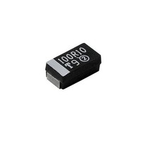
Tantalum Capacitors - Solid SMD 330uF 10volts 10% E case
Manufacturer
Vishay
Series
293Dr
Datasheet
1.293D337X06R3E2T.pdf
(13 pages)
Specifications of 293D337X9010E2T
Capacitance
330 uF
Voltage Rating
10 Volts
Esr
0.5 Ohms
Tolerance
10 %
Operating Temperature Range
- 55 C to + 85 C
Package / Case
7343-43 metric
Dimensions
4.3 mm W x 7.3 mm L
Height
4 mm
Mfr Case Code
E Case
Product
Tantalum Solid Low ESR Commercial Grade
Dissipation Factor Df
10
Lead Spacing
1.3 mm
Leakage Current
33 uAmps
Ripple Current
0.57 Amp
Termination Style
SMD/SMT
Lead Free Status / Rohs Status
No RoHS Version Available


www.vishay.com
9
293D
Vishay Sprague
PERFORMANCE CHARACTERISTICS
8.
8.1
9.
9.1
10.
10.1
10.2
10.2.1 Vibration frequency shall be varied uniformly between
10.2.2 An oscilloscope or other comparable means shall be
10.2.3 Electrical tests shall show no evidence of intermittent
10.2.4 Following the low frequency vibration test, capacitors
10.3
10.3.1 Vibration frequency shall be varied logarithmically
10.3.2 The vibration shall be applied for 4 hours in each of 2
10.3.3 Rated DC voltage shall be applied during the vibration
10.3.4 An oscilloscope or other comparable means shall be
ESR
ESR (Equivalent Series Resistance) shall not
exceed the values listed in the Ratings Table.
Measurement shall be made by the bridge method at
a frequency of 100 kHz and a temperature of + 25 °C.
Life Test: Capacitors shall withstand rated DC
voltage applied at + 85 °C or two-thirds rated voltage
applied at + 125 °C for 1000 hours.
Following the life test, the dissipation factor shall meet
the initial requirement; the capacitance change shall
not exceed ± 10 %; the leakage current shall not
exceed 125 % of the initial requirement.
Vibration Tests: Capacitors shall be subjected to
vibration tests in accordance with the following
criteria.
Capacitors shall be secured for test by means of a
rigid mounting using suitable brackets.
Low Frequency Vibration: Vibration shall consist of
simple harmonic motion having an amplitude of
0.03" [0.76 mm] and a maximum total excursion of
0.06" [1.52 mm], in a direction perpendicular to the
major axis of the capacitors.
the approximate limits of 10 Hz to 55 Hz during a
period of approximately one minute, continuously for
1.5 hours.
used in determining electrical intermittency during the
final 30 minutes of the test. The AC voltage applied
shall not exceed 2 volts rms.
contacts, open circuits or short circuits during these
tests.
shall meet the original requirements for capacitance,
dissipation factor and leakage current.
High Frequency Vibration: Vibration shall consist of
a simple harmonic motion having an amplitude of
0.06" [1.52] ± 10 % maximum total excursion or 20 g
peak whichever is less.
from 50 Hz to 2000 Hz and return to 50 Hz during a
cycle period of 20 minutes.
directions, parallel and perpendicular to the major
axis of the capacitors.
cycling.
used in determining electrical intermittency during the
TANTAMOUNT®, Commercial, Surface Mount
For technical questions, contact: tantalum@vishay.com
Solid Tantalum Chip Capacitors
(Continued)
10.3.5 Electrical tests shall show no evidence of intermittent
10.3.6 There shall be no mechanical damage to these
10.3.7 Following the high frequency vibration test, capacitors
11.
11.1
11.2
11.2.1 The direction of motion shall be parallel to and
11.3
11.3.1 An oscilloscope or other comparable means shall be
11.4
11.5
11.6
12.
12.1
12.1.1 Test equipment shall be adjusted to produce a shock
12.2
12.3
12.3.1 An oscilloscope or other comparable means shall be
last cycle. The AC voltage applied shall not exceed 2
volts rms.
contacts, open circuits or short circuits during these
tests.
capacitors as a result of these tests.
shall meet the original limits for capacitance,
dissipation factor and leakage current.
Acceleration Test:
Capacitors shall be rigidly mounted by means of
suitable brackets.
Capacitors shall be subjected to a constant
acceleration of 100 g for a period of 10 seconds in
each of 2 mutually perpendicular planes.
per-pendicular to the longitudinal axis of the
capacitors.
Rated DC voltage shall be applied during acceleration
test.
used in determining electrical intermittency during
test. The AC voltage applied shall not exceed 2 volts
rms.
Electrical tests shall show no evidence of intermittent
contacts, open circuits or short circuits during these
tests.
There shall be no mechancial damage to these
capacitors as a result of these tests.
Following the acceleration test, capacitors shall meet
the original limits for capacitance, dissipation factor
and leakage current.
Shock Test:
Capacitors shall be rigidly mounted by means of
suitable brackets. The test load shall be distributed
uniformly on the test platform to minimize the effects
of unbalanced loads.
of 100 g peak with the duration of 6 mS and sawtooth
waveform at a velocity change of 9.7 ft./sec.
Capacitors shall be subjected to 3 shocks applied in
each of 3 directions corresponding to the 3 mutually
perpendicular axes of the capacitors.
Rated DC voltage shall be applied during test.
used in determining electrical intermittency during
tests. The replacement voltage applied shall not
exceed 2 volts rms.
Document Number: 40002
Revision: 25-Apr-05
Related parts for 293D337X9010E2T
Image
Part Number
Description
Manufacturer
Datasheet
Request
R

Part Number:
Description:
357-036-542-201 CARDEDGE 36POS DL .156 BLK LOPRO
Manufacturer:
Vishay
Datasheet:
Part Number:
Description:
357-036-542-201 CARDEDGE 36POS DL .156 BLK LOPRO
Manufacturer:
Vishay
Datasheet:
Part Number:
Description:
357-036-542-201 CARDEDGE 36POS DL .156 BLK LOPRO
Manufacturer:
Vishay
Datasheet:
Part Number:
Description:
357-036-542-201 CARDEDGE 36POS DL .156 BLK LOPRO
Manufacturer:
Vishay
Datasheet:
Part Number:
Description:
357-036-542-201 CARDEDGE 36POS DL .156 BLK LOPRO
Manufacturer:
Vishay
Datasheet:
Part Number:
Description:
357-036-542-201 CARDEDGE 36POS DL .156 BLK LOPRO
Manufacturer:
Vishay
Datasheet:
Part Number:
Description:
357-036-542-201 CARDEDGE 36POS DL .156 BLK LOPRO
Manufacturer:
Vishay
Datasheet:
Part Number:
Description:
357-036-542-201 CARDEDGE 36POS DL .156 BLK LOPRO
Manufacturer:
Vishay
Datasheet:
Part Number:
Description:
357-036-542-201 CARDEDGE 36POS DL .156 BLK LOPRO
Manufacturer:
Vishay
Datasheet:
Part Number:
Description:
357-036-542-201 CARDEDGE 36POS DL .156 BLK LOPRO
Manufacturer:
Vishay
Datasheet:
Part Number:
Description:
357-036-542-201 CARDEDGE 36POS DL .156 BLK LOPRO
Manufacturer:
Vishay
Datasheet:
Part Number:
Description:
357-036-542-201 CARDEDGE 36POS DL .156 BLK LOPRO
Manufacturer:
Vishay
Datasheet:
Part Number:
Description:
357-036-542-201 CARDEDGE 36POS DL .156 BLK LOPRO
Manufacturer:
Vishay
Datasheet:
Part Number:
Description:
357-036-542-201 CARDEDGE 36POS DL .156 BLK LOPRO
Manufacturer:
Vishay
Datasheet:
Part Number:
Description:
357-036-542-201 CARDEDGE 36POS DL .156 BLK LOPRO
Manufacturer:
Vishay
Datasheet: