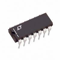
LTC1164-7CN Linear Technology, LTC1164-7CN Datasheet - Page 12

LTC1164-7CN
Manufacturer Part Number
LTC1164-7CN
Description
IC FILTR 8TH ORDER LOWPASS 14DIP
Manufacturer
Linear Technology
Datasheet
1.LTC1164-7CSWPBF.pdf
(16 pages)
Specifications of LTC1164-7CN
Filter Type
Linear Phase, Lowpass Switched Capacitor
Frequency - Cutoff Or Center
100kHz
Number Of Filters
1
Max-order
8th
Voltage - Supply
4.75 V ~ 16 V, ±2.375 V ~ 8 V
Mounting Type
Through Hole
Package / Case
14-DIP (0.300", 7.62mm)
Lead Free Status / RoHS Status
Contains lead / RoHS non-compliant
LTC1164-7
A
Transient Response
Aliasing
Aliasing is an inherent phenomenon of sampled data
systems and it occurs when input frequencies close to the
sampling frequency are applied. For the LTC1164-7 case
at 100:1, an input signal whose frequency is in the range
of f
12
PPLICATI
CLK
±3%, will be aliased back into the filter’s passband.
INPUT
INPUT = 1kHz ± 3V
f
f
V
CLK
C
S
= 10kHz
= ±7.5V
= 500kHz
RISE TIME (t
SETTLING TIME (t
(TO 1% of OUTPUT)
TIME DELAY (t
(TO 50% OF OUTPUT)
10%
90%
50%
O
U
r
) =
d
S
) = GROUP DELAY ≈
t d
f
CUTOFF
0.39
s
) =
Figure 5
Figure 6
I FOR ATIO
100µs/DIV
t s
f
U
CUTOFF
±5%
2.2
t r
±5%
f
CUTOFF
W
1.2
1164-7 F05
U
1164-7 F06
OUTPUT
If, for instance, an LTC1164-7 operating with a 100kHz
clock and 1kHz cutoff frequency receives a 98kHz 10mV
input signal, a 2kHz, 143µV
its output. When the LTC1164-7 operates with a clock-to-
cutoff frequency of 50:1, aliasing occurs at twice the clock
frequency. Table 11 shows details.
Table 11. Aliasing (f
50:1, f
190 (or 210)
195 (or 205)
196 (or 204)
197(or 203)
198 (or 202)
199.5 (or 200.5)
100:1, f
97 (or 103)
97.5 (or 102.5)
98 (or 102)
98.5 (or 101.5)
99 (or 101)
99.5 (or 100.5)
INPUT FREQUENCY
f
IN
(V
= f
CUTOFF
IN
CUTOFF
CLK
(kHz)
V
f
f
(f
= 1V
CLK
C
S
CLK
= 20kHz
= ±7.5V
± f
= 1MHz
/f
= 2kHz
RMS
C
= 1kHz
) = 50:1
OUT
,
)
CLK
Figure 7. Eye Diagram
(Relative to Input,
= 100kHz)
OUTPUT LEVEL
0dB = 1V
– 51.9
– 36.3
– 18.4
– 53.2
– 36.9
– 19.6
–76.1
–74.2
(dB)
– 3.0
– 0.2
– 5.2
– 0.7
5µs/DIV
RMS
RMS
alias signal will appear at
)
f
OUTPUT FREQUENCY
OUT
(Aliased Frequency
= ABS [f
1164-7 F07
(kHz)
10.0
5.0
4.0
3.0
2.0
0.5
3.0
2.5
2.0
1.5
1.0
0.5
CLK
± f
11647fb
IN
])


