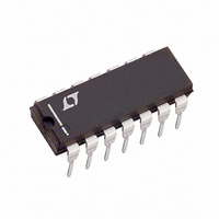
LTC1064-2CN#PBF Linear Technology, LTC1064-2CN#PBF Datasheet - Page 3

LTC1064-2CN#PBF
Manufacturer Part Number
LTC1064-2CN#PBF
Description
IC FILTR 8TH ORDR LOWPASS 14-DIP
Manufacturer
Linear Technology
Datasheet
1.LTC1064-2CNPBF.pdf
(12 pages)
Specifications of LTC1064-2CN#PBF
Filter Type
Butterworth, Lowpass Switched Capacitor
Frequency - Cutoff Or Center
140kHz
Number Of Filters
1
Max-order
8th
Voltage - Supply
±2.375 V ~ 8 V
Mounting Type
Through Hole
Package / Case
14-DIP (0.300", 7.62mm)
Leaded Process Compatible
Yes
Rohs Compliant
Yes
Peak Reflow Compatible (260 C)
Yes
Filter Order
8th
No. Of Filters
1
Cutoff Frequency
140kHz
Supply Voltage Range
± 2.37V To ± 8V
Operating Temperature Range
-40°C To +85°C
Filter Ic Case Style
DIP
No. Of Pins
14
Lead Free Status / RoHS Status
Lead free / RoHS Compliant
Available stocks
Company
Part Number
Manufacturer
Quantity
Price
ELECTRICAL CHARACTERISTICS
PARAMETER
Output DC Offset (Note 2)
Output DC Offset TempCo
Input Impedance
Output Impedance
Output Short-Circuit Current
Clock Feedthrough
Maximum Clock Frequency
Power Supply Current
Power Supply Voltage Range
Note 1: Absolute Maximum Ratings are those values beyond which the life
of a device may be impaired.
temperature range, otherwise specifications are at T
otherwise specified.
TYPICAL PERFOR A CE CHARACTERISTICS
–105
–15
–30
–45
–60
–75
–90
15
0
10k
Amplitude Response
f
f–3dB = 40kHz
V
T
CLK
f
f–3dB = 100kHz
CLK
A
S
= 25°C
= ±7.5V; 50:1
= 2MHz
= 5MHz
f
IN
100k
(Hz)
f
f–3dB = 140kHz
CLK
= 7MHz
W
1064 G01
CONDITIONS
V
V
f
Source/Sink
50% Duty Cycle, V
50% Duty Cycle, T
V
V
V
OUT
S
S
S
S
S
U
1M
= ±7.5V
= ±5V
= ±2.37V, f
= ±5V, f
= ±7.5V, f
= 10kHz
CLK
–135
–180
–225
–270
–315
–360
–405
–450
CLK
–45
–90
CLK
= 1MHz
45
0
= 1MHz
A
0
Phase Response
S
A
= 1MHz
= 25°C. V
= 25°C, V
= ±5V
1
The
2
3
S
S
= ±7.5V
4
denotes the specifications which apply over the full operating
= ±7.5V, 100:1, f
f
IN
5
(kHz)
Note 2: For tighter specifications please contact LTC Marketing.
6
7
V
T
f
100:1
f
CLK
–3dB
A
S
8
= ±7.5V
= 25°C
= 1MHz
= 10kHz
9
CLK
10
1064 G02
= 2MHz, R1 = 10k, TTL clock input level unless
11
220
200
180
160
140
120
100
80
60
40
20
0
0
Group Delay vs Frequency
V
T
f
100:1
f
–3dB
CLK
±2.37
A
S
MIN
1
10
= 25°C
= ±7.5V
= 1MHz
= 10kHz
2
3
LTC1064-2
TYP
±30
±90
200
4
3/1
14
20
11
17
2
f
IN
5
(kHz)
6
±125
MAX
7
±8
22
23
26
28
32
5
7
8
9 10 11
µV
UNITS
10642fa
1064 G03
µV/°C
3
MHz
MHz
RMS
mV
mA
mA
mA
mA
mA
mA
kΩ
Ω
V


