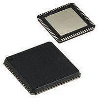
AT90USB1287-16MU Atmel, AT90USB1287-16MU Datasheet - Page 8

AT90USB1287-16MU
Manufacturer Part Number
AT90USB1287-16MU
Description
Microcontrollers (MCU) 128kB Flash 4kB EEPROM 48 I/O Pins
Manufacturer
Atmel
Datasheet
1.AT90USB1287-16MU.pdf
(30 pages)
Specifications of AT90USB1287-16MU
Data Bus Width
8 bit
Program Memory Type
Flash
Program Memory Size
128 KB
Data Ram Size
8 KB
Interface Type
2-Wire, SPI, USART
Maximum Clock Frequency
16 MHz
Number Of Programmable I/os
48
Number Of Timers
4
Operating Supply Voltage
2.7 V to 5.5 V
Maximum Operating Temperature
+ 85 C
Mounting Style
SMD/SMT
Package / Case
QFN-64
Minimum Operating Temperature
- 40 C
On-chip Adc
10 bit
Lead Free Status / Rohs Status
Details
Other names
AT90USB1287-MU
Available stocks
Company
Part Number
Manufacturer
Quantity
Price
Part Number:
AT90USB1287-16MU
Manufacturer:
ATMEL/爱特梅尔
Quantity:
20 000
2.2.9
2.2.10
2.2.11
2.2.12
2.2.13
2.2.14
2.2.15
2.2.16
2.2.17
2.2.18
2.2.19
3. About Code Examples
8
AT90USB64/128
D-
D+
UGND
UVCC
UCAP
VBUS
RESET
XTAL1
XTAL2
AVCC
AREF
USB Full speed / Low Speed Negative Data Upstream Port. Should be connected to the USB D-
connector pin with a serial 22 Ohms resistor.
USB Full speed / Low Speed Positive Data Upstream Port. Should be connected to the USB D+
connector pin with a serial 22 Ohms resistor.
USB Pads Ground.
USB Pads Internal Regulator Input supply voltage.
USB Pads Internal Regulator Output supply voltage. Should be connected to an external capac-
itor (1µF).
USB VBUS monitor and OTG negociations.
Reset input. A low level on this pin for longer than the minimum pulse length will generate a
reset, even if the clock is not running. The minimum pulse length is given in
58. Shorter pulses are not guaranteed to generate a reset.
Input to the inverting Oscillator amplifier and input to the internal clock operating circuit.
Output from the inverting Oscillator amplifier.
AVCC is the supply voltage pin for Port F and the A/D Converter. It should be externally con-
nected to V
through a low-pass filter.
This is the analog reference pin for the A/D Converter.
This documentation contains simple code examples that briefly show how to use various parts of
the device. Be aware that not all C compiler vendors include bit definitions in the header files
and interrupt handling in C is compiler dependent. Please confirm with the C compiler documen-
tation for more details.
These code examples assume that the part specific header file is included before compilation.
For I/O registers located in extended I/O map, "IN", "OUT", "SBIS", "SBIC", "CBI", and "SBI"
CC
, even if the ADC is not used. If the ADC is used, it should be connected to V
Table 8-1 on page
7593GS–AVR–03/08
CC


