N1914A-107 AGILENT TECHNOLOGIES, N1914A-107 Datasheet
N1914A-107
Specifications of N1914A-107


N1914A-107 Summary of contents
Page 1
... VGA output option 1. Additional two optional USB channels available (see Ordering Information, page 10) 2. Only applicable for models with battery option (see Ordering Information, page 10) 3. N1913A is backward compatible with the 436A and 437B, while N1914A is compatible with 438A 2 —and get extra operating ...
Page 2
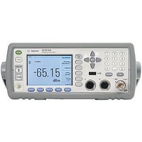
... Hard keys provide quick access to the most frequently used functions, such as Trigger and Acquisition N1914A back panel Rear-panel sensor and Power Ref connectors provide an option to replace front-panel connectors Optional trigger in and out connectors ...
Page 3
N1913A/14A Series Power Meter: Applications and Compatible Sensors for Average Power Measurements Signal characteristics > CW Pulse/ CW averaged Typical application Metrology Radar/ examples > lab navigation Themocouple sensors: ● ● 8480A/B/H, N8480A/B/H, R/Q8486A, N8486AR/AQ Diode sensors: ● ● 8480D, ...
Page 4
N1913A/14A EPM Series Power Meters Performance Characteristics Specifications describe the instrument’s warranted performance and apply after a 30 minute warm-up. These specifications are valid over its operating/ environmental range unless otherwise stated and after performing a zero and calibration procedure. ...
Page 5
... With N1913A power meter • Normal: 20 readings/second • x2: 40 readings/second • Fast: 400 readings/second With N1914A power meter The measurement speed is reduced, for example, with both channels in FAST mode, the typical maximum measurement speed is 200 readings/second. Fast mode is for Agilent E-Series power sensors only. ...
Page 6
... E-Series sensors In FAST mode (using free run trigger), within the range –50 dBm to +17 dBm, for decreasing power step, the settling time is: 2 N1913A N1914A Settling time 99% settled readings over the GPIB. 2. When a power step crosses through the sensor’s auto-range switch point, add 25 ms. Refer to the relevant sensor manual for switch point information ...
Page 7
N1913A/14A EPM Series Power Meters Performance Characteristics Settling time (continued) Auto filter decreasing power step for normal and X2 modes (not across the range switch points for E-Series and N8480 Series sensors). x2 Normal speed speed Typical 40 ...
Page 8
... Weight Model N1913A N1914A Rear panel connectors Recorder outputs Analog Volt, 1 kΩ output impedance, BNC connector. N1914A recorder outputs are dedicated to channel A and channel B. GPIB, USB 2.0 and Interfaces to allow communication with an external controller 10/100BaseT LAN Trigger Input (optional) Input has TTL compatible logic levels and uses a BNC connector. ...
Page 9
N1913A/14A EPM Series Power Meters Performance Characteristics Line power Input voltage range 90 to 264 VAC, automatic selection Input frequency range and 400 Hz @ 110 Vac Power requirement 75 VA (50 Watts) Battery option operational ...
Page 10
... N1914A Dual-channel average power meter Standard-shipped accessories Power cord Power sensor cable, 1 ft) (One per N1913A, two per N1914A) USB cable Type A to Mini- Hard copy English language User’s Guide and Installation Guide Product CD-ROM (contains English and localized User’s Guide and ...
Page 11
E-Series Power Sensor Specifications The E-Series of power sensors have their calibration factors stored in EEPROM and operate over a wide dynamic range. They are designed for use with the EPM Series of power meters and two classes of sensors ...
Page 12
E-Series CW Power Sensor Specifications Calibration factor (CF) and reflection coefficient (Rho) Calibration factor and reflection coefficient data are provided at 1 GHz increments on a data sheet included with the power sensor. This data is unique to each sensor. ...
Page 13
E-Series CW Power Sensor Specifications Power linearity Table 6. E4410 Series power linearity specification Power 100 (–70 dBm to +10 dBm 100 mW (+10 dBm to +20 dBm) +20 + –20 ...
Page 14
E-Series E9300 Average Power Sensor Specifications The E-Series E9300 wide dynamic range, average power sensors are designed for use with the EPM family of power meters. These specifications are valid ONLY after proper calibration of the power meter and apply ...
Page 15
E-Series E9300 Average Power Sensor Specifications 1.2 1.18 1.16 1.14 1.12 1.1 1.08 1.06 1.04 1.02 1 0.01 2.00 4.00 6.00 8.00 10.00 12.00 14.00 16.00 18.00 Frequency GHz Typical SWR, 10 MHz to 18 GHz (25 °C ±10 °C) ...
Page 16
E-Series E9300 Average Power Sensor Specifications Power linearity* Table 9. E9300 Series power linearity (after zero and cal at ambient environmental conditions) sensor Sensor Power E9300A, E9301A, E9304A –60 to –10 dBm – dBm 0 to +20 dBm ...
Page 17
E-Series E9300 Average Power Sensor Specifications Effects of change in temperature on linearity Note: If the temperature changes after calibration and you choose not to re-calibrate the sensor, the follow- ing additional power linearity error should be added to the ...
Page 18
E-Series E9300 Average Power Sensor Specifications Switch point data The E9300 power sensors have two paths as shown in Table 7. The power meter automatically selects the proper power level path. To avoid unnecessary switching when the power level is ...
Page 19
E-Series E9300 Average Power Sensor Specifications Calibration factor (CF) and reflection coefficient (Rho) Calibration factor and reflection coefficient data are provided at frequency intervals on a data sheet included with the power sensor. This data is unique to each sensor. ...
Page 20
Series Diode and 8483A Thermocouple Power Sensor Specifications Calibration factor uncertainties These thermocouple and diode power sensors provide extraordinary accuracy, stability, and SWR over a wide range of frequencies (100 kHz to 110 GHz) and power levels (–70 dBm ...
Page 21
Series Diode and 8483A Thermocouple Power Sensor Specifications (continued) Maximum SWR and power linearity Table 14. 8480 Series maximum SWR and power linearity Frequency Maximum Model range SWR 100 mW sensors, 1 μW to 100 mW (–30 dBm to ...
Page 22
N8480 Series Thermocouple Power Sensor Specifications The N8480 Series power sensors (excluding Option CFT) measure power levels from –35 dBm to +44 dBm (316 nW to 25.1 W), at frequencies from 100 kHz to 50 GHz and have two independent ...
Page 23
N8480 Series Thermocouple Power Sensor Specifications Maximum SWR and power linearity for standard N8480 Series power sensors Table 16. N8480 Series maximum SWR and power linearity Frequency Maximum 1 Model range SWR 3 100 mW sensors. Power range : 316 ...
Page 24
N8480 Series Thermocouple Power Sensor Specifications Switch point data Switching point is applicable for standard N8480 Series power sensors only. The N8480 Series power sensors have two power measurement ranges; a lower range and upper range. The power meter automatically ...
Page 25
U2000 Series USB Power Sensor Specifications The U2000 Series USB power sensors are true average, wide-dynamic-range RF/microwave power sensors, based on a dual-sensor diode pair/attenuator/ diode pair topology. The U2000 Series USB power sensors can be operated on N1913A/14A via ...
Page 26
U2000 Series USB Power Sensor Specifications Maximum SWR Table 19. U2000 Series USB sensors maximum SWR Model Frequency range U2000A 10 MHz to 30 MHz 30 MHz to 2 GHz 2 GHz to 14 GHz 14 GHz to 16 GHz ...
Page 27
... Spain 34 (91) 631 3300 Sweden 0200- Switzerland 0800 United Kingdom 44 (0) 118 9276201 Other European Countries: www.agilent.com/find/contactus Revised: July 8, 2010 Product specifications and descriptions in this document subject to change without notice. © Agilent Technologies, Inc. 2010 Printed in USA, October 12, 2010 5990-4019EN ...