XRU1D24U EATON CUTLER HAMMER, XRU1D24U Datasheet - Page 6
XRU1D24U
Manufacturer Part Number
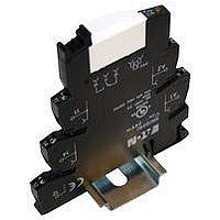
XRU1D24U
Description
TERM BLK RELAY, 24VAC/VDC, 1PDT, SCREW, DIN RAIL MT
Manufacturer
EATON CUTLER HAMMER
Series
XRr
Datasheet
1.XRU1D120U.pdf
(12 pages)
Specifications of XRU1D24U
Contact Current Max
6A
Contact Voltage Dc Max
24V
Contact Configuration
1PDT
Relay Mounting
DIN Rail
External Width
6.2mm
Contact Voltage Ac Max
24V


6
Permissible Range Diagrams
1PDT
Figure 5. Operating Range Voltage for 12V DC
1PDT Relay Module
Figure 6. Operating Range Voltage for
120V AC/110V DC 1PDT Relay Module
DPDT
Figure 9. Operating Range Voltage for 12V DC
DPDT Relay Module
Figure 10. Operating Range Voltage for
120V AC/110V DC DPDT Relay Module
U
U
U
U
U
U
U
U
N
N
N
N
XR Series Terminal Block Relays
Standard Terminal Block Relays
1.4
1.3
1.2
1.1
1.0
0.9
0.8
0.7
1.4
1.3
1.2
1.1
1.0
0.9
0.8
0.7
1.4
1.3
1.2
1.1
1.0
0.9
0.8
0.7
1.4
1.3
1.2
1.1
1.0
0.9
0.8
0.7
20 25 30
20 25 30
20 25 30
20 25 30
U
U
U
N
N
N
U
U
A
A
A
B
= 110V DC/120V AC
B
B
= 120V AC
= 110V DC
B
N
N
= 12V DC
= 12V DC
35 40 45 50 55 60 65
35 40 45 50 55 60 65
35 40 45 50 55 60 65
35 40 45 50 55 60 65
A
T
T
T
T
N
N
N
N
[°C]
[°C]
[°C]
[°C]
For more information visit: www.EatonElectrical.com
Figure 7. Operating Range Voltage for 24V DC
1PDT Relay Module
Figure 8. Operating Range Voltage for
24V AC/DC 1PDT Relay Module
Figure 11. Operating Range Voltage for
24V DC DPDT Relay Module
Figure 12. Operating Range Voltage for
24V AC/DC DPDT Relay Module
U
U
U
U
U
U
U
U
N
N
N
N
1.4
1.3
1.2
1.1
1.0
0.9
0.8
0.7
1.4
1.3
1.2
1.1
1.0
0.9
0.8
0.7
1.4
1.3
1.2
1.1
1.0
0.9
0.8
0.7
1.4
1.3
1.2
1.1
1.0
0.9
0.8
0.7
20 25 30
20 25 30
20 25 30
20 25 30
U
U
N
N
U
U
A
B
A
= 24V DC/24V AC
B
A
B
A
= 24V DC/24V AC
B
N
N
= 24V DC
= 24V DC
35 40 45 50 55 60 65
35 40 45 50 55 60 65
35 40 45 50 55 60 65
35 40 45 50 55 60 65
T
T
T
T
N
N
N
N
[°C]
[°C]
[°C]
[°C]
Notes:
General Conditions — Direct alignment in
the block, all devices 100% operating factor,
horizontal or vertical mounting.
Curve A — Maximum permissible continu-
ous operating voltage U max with limiting
continuous current on the contact side (see
respective technical data).
Curve B — Minimum permissible relay
operate voltage U op after pre-excitation )
(see respective technical data).
Pre-excitation: Relay has been operated in a
thermally steady state at the ambient tem-
perature T U with nominal voltage U N and
limiting continuous current on the contact
side (see respective technical data) (warm
coil). After being switched off for a short
time, the relay must reliably pick up again at
U op .
CA04900001E
March 2006
Related parts for XRU1D24U
Image
Part Number
Description
Manufacturer
Datasheet
Request
R

Part Number:
Description:
PROGRAMMABLE LOGIC CONTROLLER
Manufacturer:
EATON CUTLER HAMMER
Part Number:
Description:
Pm Power Pro 3000/5000 A-B Accel/On Interface
Manufacturer:
EATON CUTLER HAMMER
Part Number:
Description:
Handle Tie Bar For (2) - 1 Pole Type BR Breakers
Manufacturer:
EATON CUTLER HAMMER
Part Number:
Description:
Type CH Breaker 150A/2 Pole 120/240V 10K
Manufacturer:
EATON CUTLER HAMMER
Part Number:
Description:
Tenant Branch Breaker 125A/3 Pole 120/240V 42K
Manufacturer:
EATON CUTLER HAMMER
Part Number:
Description:
Type CL Breaker 25A/1Pole 120/240V 10K-Classified 1" Ckt Bkr
Manufacturer:
EATON CUTLER HAMMER
Part Number:
Description:
FD BREAKER 1P 80 AMP WITH LOAD ONLY TERMINALS
Manufacturer:
EATON CUTLER HAMMER
Part Number:
Description:
GD 2 POLE BREAKER, 25 AMP, SINGLE PACKED
Manufacturer:
EATON CUTLER HAMMER
Part Number:
Description:
Handle Tie Bar For (2) - 1 Pole Type BR Breakers
Manufacturer:
EATON CUTLER HAMMER
Part Number:
Description:
Type CL Breaker 25A/1Pole 120/240V 10K-Classified 1" Ckt Bkr
Manufacturer:
EATON CUTLER HAMMER