MRF136 M/A-COM Technology, MRF136 Datasheet - Page 11
MRF136
Manufacturer Part Number
MRF136
Description
RF MOSFET Power 5-400MHz 15Watts 28Volt Gain 16dB
Manufacturer
M/A-COM Technology
Datasheet
1.MRF136.pdf
(12 pages)
Specifications of MRF136
Configuration
Single
Drain-source Breakdown Voltage
65 V
Gate-source Breakdown Voltage
40 V
Continuous Drain Current
2.5 A
Power Dissipation
55 W
Maximum Operating Temperature
+ 150 C
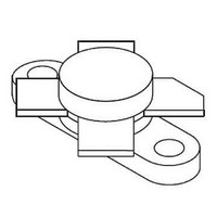
Package / Case
Case 211-07
Minimum Operating Temperature
- 65 C
Transistor Polarity
N-Channel
Lead Free Status / Rohs Status
Details
Available stocks
Company
Part Number
Manufacturer
Quantity
Price
Company:

Part Number:
MRF136
Manufacturer:
MA/COM
Quantity:
5 000
Part Number:
MRF136
Manufacturer:
ASI
Quantity:
20 000
Part Number:
MRF136-1
Manufacturer:
ASI
Quantity:
20 000
Company:
Part Number:
MRF136MP
Manufacturer:
MA/COM
Quantity:
5 000
Part Number:
MRF136MP
Manufacturer:
M/A-COM
Quantity:
20 000
Company:
Part Number:
MRF136Y
Manufacturer:
m/a-com
Quantity:
5 000
Part Number:
MRF136Y
Manufacturer:
ASI
Quantity:
20 000


11
ADVANCED: Data Sheets contain information regarding a product M/A-COM Technology Solutions
is considering for development. Performance is based on target specifications, simulated results,
and/or prototype measurements. Commitment to develop is not guaranteed.
PRELIMINARY: Data Sheets contain information regarding a product M/A-COM Technology
Solutions has under development. Performance is based on engineering tests. Specifications are
typical. Mechanical outline has been fixed. Engineering samples and/or test data may be available.
Commitment to produce in volume is not guaranteed.
The RF MOSFET Line
15W, to 400MHz, 28V
MRF136
DESIGN CONSIDERATIONS
mode field–effect transistor (FET) designed especially for
VHF power amplifier applications. M/A-COM RF MOS
FETs feature a vertical structure with a planar design, thus
avoiding the processing difficulties associated with V–
groove vertical power FETs.
Practice, is suggested reading for those not familiar with
the construction and characteristics of FETs.
gain, low noise, simple bias systems, relative immunity
from thermal runaway, and the ability to withstand severely
mismatched loads without suffering damage. Power output
can be varied over a wide range with a low power dc con-
trol signal, thus facilitating manual gain control, ALC and
modulation.
DC BIAS
fore, does not conduct when drain voltage is applied. Drain
current flows when a positive voltage is applied to the gate.
See Figure 10 for a typical plot of drain current versus gate
voltage. RF power FETs require forward bias for optimum
performance.
formany applications. The MRF137 was characterized at
I
For special applications such as linear amplification, I
may have to be selected to optimize the critical parameters.
fore, the gate bias circuit may generally be just a simple
DQ
The MRF137 is a RF power N–Channel enhancement-
M/A-COM Application Note AN211A, FETs in Theory and-
The major advantages of RF power FETs include high
The MRF137 is an enhancement mode FET and, there-
The value of quiescent drain current (I
The gate is a dc open circuit and draws no current. There-
= 25 mA, which is the suggested minimum value of I
RF POWER MOSFET CONSIDERATIONS
DQ
) is not critical
DQ
DQ
.
resistive divider network. Some special applications may
require a more elaborate bias system.
GAIN CONTROL
its rated value down to zero (negative gain) by varying the
dc gate voltage. This feature facilitates the design of man-
ual gain control, AGC/ALC and modulation systems. (See
Figure 9.)
AMPLIFIER DESIGN
with bipolar VHF transistors are suitable for MRF137. See
M/A-COM Application Note AN721, Impedance Matching
Networks Applied to RF Power Transistors. The higher
input impedance of RF MOS FETs helps ease the task of
broadband network design. Both small signal scattering
parameters and large signal impedances are provided.
While the s–parameters will not produce an exact design
solution for high power operation, they do yield a good first
approximation. This is an additional advantage of RF MOS
power FETs.
unilateral. This, coupled with the very high gain of the
MRF137, yields a device capable of self oscillation. Stabil-
ity may be achieved by techniques such as drain loading,
input shunt resistive loading, or output to input feedback.
Two port parameter stability analysis with the MRF137 s–
parameters provides a useful tool for selection of loading or
feedback circuitry to assure stable operation. See M/A-
COM Application Note AN215A for a discussion of two port
network theory and stability.
LOW NOISE OPERATION
Input resistive loading will degrade noise performance, and
noise figure may vary significantly with gate driving imped-
ance. A low loss input matching network with its gate im-
pedance optimized for lowest noise is recommended.
M/A-COM Technology Solutions Inc. and its affiliates reserve the right to make
changes to the product(s) or information contained herein without notice.
• North America Tel: 800.366.2266 / Fax: 978.366.2266
• Europe Tel: 44.1908.574.200 / Fax: 44.1908.574.300
• Asia/Pacific Tel: 81.44.844.8296 / Fax: 81.44.844.8298
Power output of the MRF137 may be controlled from
Impedance matching networks similar to those used
RF power FETs are triode devices and, therefore, not
Visit www.macomtech.com for additional data sheets and product information.
M/A-COM Products
Released - Rev. 05202009
Related parts for MRF136
Image
Part Number
Description
Manufacturer
Datasheet
Request
R
