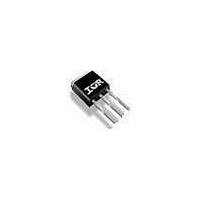
VS-20UT04 Vishay, VS-20UT04 Datasheet - Page 2

VS-20UT04
Manufacturer Part Number
VS-20UT04
Description
Schottky (Diodes & Rectifiers) 20 Amp 45 Volt 900 Amp IFSM
Manufacturer
Vishay
Datasheet
1.20UT04.pdf
(7 pages)
Specifications of VS-20UT04
Product
Schottky Diodes
Peak Reverse Voltage
45 V
Forward Continuous Current
20 A
Max Surge Current
900 A
Configuration
Single Dual Anode
Forward Voltage Drop
0.48 V
Maximum Reverse Leakage Current
100 uA
Operating Temperature Range
- 55 C to + 175 C
Mounting Style
Through Hole
Package / Case
IPAK (TO-251AA)
Lead Free Status / Rohs Status
Details
Available stocks
Company
Part Number
Manufacturer
Quantity
Price
Part Number:
VS-20UT04
Manufacturer:
VISHAY/威世
Quantity:
20 000
VS-20UT04, VS-20WT04FN
Vishay Semiconductors
Note
(1)
Notes
(1)
(2)
www.vishay.com
2
ABSOLUTE MAXIMUM RATINGS
PARAMETER
Maximum average forward current
Maximum peak one cycle
non-repetitive surge current
Non-repetitive avalanche energy
Repetitive avalanche current
ELECTRICAL SPECIFICATIONS
PARAMETER
Forward voltage drop
Reverse leakage current
Junction capacitance
Series inductance
Maximum voltage rate of change
THERMAL - MECHANICAL SPECIFICATIONS
PARAMETER
Maximum junction and
storage temperature range
Maximum thermal resistance,
junction to case
Typical thermal resistance,
case to heatsink
Approximate weight
Marking device
Measured connecting 2 anode pins
Pulse width < 300 μs, duty cycle < 2 %
Only 1 anode pin connected
DiodesAmericas@vishay.com, DiodesAsia@vishay.com,
For technical questions within your region, please contact one of the following:
SYMBOL
SYMBOL
SYMBOL
V
T
I
FM
dV/dt
R
R
I
J
RM
I
E
F(AV)
FSM
, T
I
C
L
thCS
thJC
AR
AS
S
T
(1)(2)
(1)
Stg
High Performance Schottky
50 % duty cycle at T
5 μs sine or 3 μs rect. pulse
10 ms sine or 6 ms rect. pulse
T
Limited by frequency of operation and time pulse duration
so that T
10 A
20 A
10 A
20 A
T
T
V
Measured lead to lead 5 mm from package body
Rated V
DC operation
Case style I-PAK
Case style D-PAK
J
J
J
R
Generation 5.0, 20 A
= 25 °C, I
= 25 °C
= 125 °C
= 5 V
R
DC
J
< T
(test signal range 100 kHz to 1 MHz), 25 °C
AS
J
max. I
= 7 A, L = 4.4 mH
TEST CONDITIONS
TEST CONDITIONS
TEST CONDITIONS
AS
C
= 153 °C, rectangular waveform
at T
J
max. as a function of time pulse
T
T
V
J
J
R
DiodesEurope@vishay.com
Following any rated load
condition and with rated
V
= 25 °C
= 125 °C
= Rated V
RRM
applied
R
(1)
- 55 to 175
0.505
0.570
0.415
0.520
Document Number: 94573
TYP.
1900
VALUES
VALUES
T
-
-
-
-
0.07
I
J
1.2
0.3
AS
900
220
108
20
2
max.
Revision: 04-Jan-11
at
20WT04FN
20UT04
10 000
MAX.
0.540
0.610
0.580
0450
100
7
-
-
UNITS
UNITS
°C/W
oz.
°C
UNITS
mJ
g
A
A
A
V/μs
mA
nH
μA
pF
V


