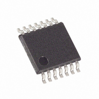
MAX3346EEUD+T Maxim Integrated Products, MAX3346EEUD+T Datasheet - Page 12

MAX3346EEUD+T
Manufacturer Part Number
MAX3346EEUD+T
Description
IC USB TXRX ESD PROTECT 14TSSOP
Manufacturer
Maxim Integrated Products
Type
Transceiverr
Datasheet
1.MAX3346EEBET.pdf
(17 pages)
Specifications of MAX3346EEUD+T
Number Of Drivers/receivers
1/1
Protocol
USB 2.0
Voltage - Supply
4 V ~ 5.5 V
Mounting Type
Surface Mount
Package / Case
14-TSSOP
Lead Free Status / RoHS Status
Lead free / RoHS Compliant
Two external resistors are required for USB connection,
each of them from 23.7Ω ±1% to 27.4Ω ±1%, 1/2W (or
greater). Place one resistor in series between D+ of the
MAX3346E and D+ of the USB connector. Place the
other resistor in series between D- of the MAX3346E
and D- of the USB connector. The Typical Operating
Circuit shows these connections.
Four external capacitors are recommended for proper
operation. Use a 0.1µF ceramic for decoupling V
1µF ceramic capacitor for decoupling V
(or greater) ceramic or plastic filter capacitor on VTRM.
Return all capacitors to GND.
Data received from the USB are output to VP/VM and
RCV in either of two ways, differentially or single ended.
To receive data from the USB, force OE high, and force
SUSP low. Differential data arriving at D+/D- appears
as differential logic signals at VP/VM, and as a single-
ended logic signal at RCV. If both D+ and D- are low,
then VP and VM are low, signaling an SE0 condition on
the bus; RCV retains the last state before SE0 (see
Table 3).
The MAX3346E outputs data to the USB differentially on
D+ and D-. The logic driving the signals may be either
differential or single ended. For sending differential
logic, force MODE high, force OE and SUSP low, and
apply data to VP and VM. If sending single-ended
logic, force MODE, SUSP, OE, and VM low, and apply
data to VP. With VP low, D+ is low and D- high, result-
ing in a logic 0 state. With VP high, D+ is high and D-
low, resulting in a logic 1 state (see Table 3).
To protect the MAX3346E against ESD, D+ and D- have
extra protection against static electricity to protect the
device up to ±15kV. The ESD structures withstand high
ESD in all states; normal operation, suspend, and pow-
ered down. For the 15kV ESD structures to work cor-
rectly, a 1µF or greater capacitor must be connected
from VTRM to GND.
±15kV ESD-Protected USB Transceiver
in UCSP
12
______________________________________________________________________________________
Transmitting Data to the USB
Receiving Data from the USB
External Components
ESD protection
External Capacitors
External Resistors
CC
, and a 1.0µF
L
, a
ESD protection can be tested in various ways; the D+
and D- input/output pins are characterized for protection
to the following limits:
1) ±15kV using the Human Body Model.
3) ±10kV using the IEC 1000-4-2 Air-Gap method.
ESD performance depends on a variety of conditions.
Contact Maxim for a reliability report that documents
test setup, test methodology, and test results.
Figure 6a shows the Human Body Model, and Figure 6b
shows the current waveform it generates when dis-
charged into a low impedance. This model consists of a
100pF capacitor charged to the ESD voltage of interest,
which is then discharged into the test device through a
1.5kΩ resistor.
2) ±8kV using the Contact Discharge method specified
Figure 6a. Human Body ESD Test Models
Figure 6b. Human Body Model Current Waveform
AMPERES
VOLTAGE
in IEC 1000-4-2.
SOURCE
HIGH-
DC
I
P
36.8%
100%
90%
10%
CHARGE-CURRENT
0
LIMIT RESISTOR
0
t
1MΩ
RL
R
100pF
C
C s
STORAGE
CAPACITOR
CURRENT WAVEFORM
TIME
1500Ω
RESISTANCE
DISCHARGE
R
D
t
DL
I r
ESD Test Conditions
Human Body Model
PEAK-TO-PEAK RINGING
(NOT DRAWN TO SCALE)
DEVICE
UNDER
TEST


