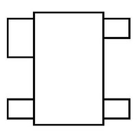
CAT812ZTBI-T10 ON Semiconductor, CAT812ZTBI-T10 Datasheet - Page 2

CAT812ZTBI-T10
Manufacturer Part Number
CAT812ZTBI-T10
Description
Supervisory Circuits 2.32V Push-Pull High
Manufacturer
ON Semiconductor
Datasheet
1.CAT812JTBI-GT3.pdf
(11 pages)
Specifications of CAT812ZTBI-T10
Number Of Voltages Monitored
1
Monitored Voltage
2.5 V, 3 V, 3.3 V, 5 V
Undervoltage Threshold
2.32 V
Output Type
Push-Pull
Manual Reset
Resettable
Watchdog
No Watchdog
Battery Backup Switching
No Backup
Power-up Reset Delay (typ)
240 ms
Supply Voltage (max)
5 V, 3.3 V, 3 V, 2.5 V
Supply Voltage (min)
- 0.3 V
Supply Current (typ)
8 uA
Maximum Power Dissipation
320 mW
Maximum Operating Temperature
+ 85 C
Mounting Style
SMD/SMT
Package / Case
SOT-143-4
Minimum Operating Temperature
- 40 C
Power Fail Detection
No
Overvoltage Threshold
2.35 V
Lead Free Status / Rohs Status
Lead free / RoHS Compliant
CAT811, CAT812
PIN DESCRIPTION
BLOCK DIAGRAM
Doc. No. MD-3005 Rev. V
CAT811
—
Pin Number
1
2
3
4
CAT812
—
1
2
3
4
V
V
MR
MR
CC
CC
¯¯¯¯¯¯
RESET
RESET
Name
GND
¯¯¯
MR
V
CC
TOLERANCE
TOLERANCE
BIAS
BIAS
Description
Ground
Active LOW reset. RESET
and remains low for at least 140ms after V
Active HIGH reset. RESET is asserted if V
and remains high for at least 140ms after V
threshold.
Manual Reset Input. A logic LOW on MR
active as long as MR
active low input has an internal 20kΩ pull-up resistor. The input should be
left open if not used.
Power supply voltage that is monitored.
V
V
CC
CC
REFERENCE
REFERENCE
VOLTAGE
VOLTAGE
+
–
+
–
¯¯¯ is LOW and for 140ms after MR
¯¯¯¯¯¯ is asserted if V
2
GND
GND
DIGITAL
DIGITAL
RESET
RESET
DELAY
DELAY
&
&
¯¯¯ asserts RESET. RESET remains
CAT811
CAT812
CC
V
V
CC
CC
CC
CC
CC
falls below the reset threshold
rises above the reset threshold.
falls below the reset threshold
rises above the reset
Characteristics subject to change without notice
¯¯¯ returns HIGH. The
RESET
RESET
© 2010 SCILLC. All rights reserved.


