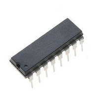
NJM#37770D3 NJR, NJM#37770D3 Datasheet - Page 2

NJM#37770D3
Manufacturer Part Number
NJM#37770D3
Description
Motor / Motion / Ignition Controllers & Drivers 60V Hi-Perf Stpr
Manufacturer
NJR
Type
Stepper Motor Driverr
Datasheet
1.NJM37770D3.pdf
(10 pages)
Specifications of NJM#37770D3
Product
Stepper Motor Controllers / Drivers
Operating Supply Voltage
5 V
Supply Current
65 mA
Mounting Style
Through Hole
Package / Case
DIP-16
Lead Free Status / Rohs Status
Lead free / RoHS Compliant
Available stocks
Company
Part Number
Manufacturer
Quantity
Price
■ PIN CONFIGURATION
■ PIN DESCRIPTION
- 2 -
12,13
3,14
DIP
4,5,
10
15
16
11
1
2
6
7
8
9
14-17
EMP
3,18
4-7
10
12
13
19
20
11
1
2
8
9
Symbol
Phase
GND
V
V
M
M
V
C
T
I
I
E
MM
CC
1
0
R
B
A
Motor output B, Motor current flows from M
Clock oscillator. Timing pin connect a 56 kΩ resistor and a 820 pF in parallel between T and
Ground.
Motor supply voltage, 10 to 40 V. Pin 3 and pin 14(EMP pin 18) should be wired to gether.
Ground and negative supply. Note these pins are used for heatsinking.
Make sure that all ground pins are soldered onto a suitable large copper ground plane for
efficient heat sinking.
Logic voltage supply normally +5 V.
Logic input. It controls, together with the I0 input, the current level in the output stage.
The controllable levels are fixed to 100, 60, 20, 0%.
Controls the direction of the motor current of M
Motor current flows from M
Logic input. It controls, together with the I
The controllable levels are fixed to 100, 60, 20, 0%.
Comparator input. This input senses the instantaneous voltage across the sensing resistor,
filtered through a RC Network.
Reference voltage. Controls the threshold voltage of the comparator and hence
the output current. Input resistance: typically 6.8 kΩ ±20%.
Motor output A, Motor current flows from M
Common emitter. Connect the Sense resistor between this pin and ground.
Figure 2. Pin configuration
A
to M
B
when the phase input is high.
Description
1
input, the current level in the output stage.
A
A
to M
to M
A
and M
B
B
when Phase is high.
when Phase is high.
B
outputs.
Ver.2006-04-11


