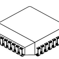
NJM3772FM2-TE3 NJR, NJM3772FM2-TE3 Datasheet - Page 6

NJM3772FM2-TE3
Manufacturer Part Number
NJM3772FM2-TE3
Description
Motor / Motion / Ignition Controllers & Drivers Dual Stepper Motor Driver
Manufacturer
NJR
Type
Stepper Motor Controller/Driverr
Datasheet
1.NJM3772FM2.pdf
(9 pages)
Specifications of NJM3772FM2-TE3
Product
Stepper Motor Controllers / Drivers
Operating Supply Voltage
10 V to 45 V
Supply Current
60 mA to 75 mA
Mounting Style
SMD/SMT
Package / Case
PLCC-28
Lead Free Status / Rohs Status
Lead free / RoHS Compliant
Current control
The output current to the motor winding is determined by the voltage at the reference input and the sensing
resistor, R
i.e., with a recommended value of
0.47 ohm for the sensing resistor R
960 mA.
To improve noise immunity on the V
changed to 1 ohm.
Figure 7. Microstepping system with NJU39610 and NJM3772
Chopping frequency, winding inductance and supply voltage also affect the current, but to much less extent.
The peak current through the sensing resistor (and motor winding) can be expressed as:
I
M,peak
APPLICATIONS INFORMATION
+2.5V
To
m P
= 0.18 • ( V
V
CC
S
.
16
27
28
15
25
(+5V)
1
7
9
D0
D7
A0
A1
WR
CS
RESET
V
Ref
Figure 6. Typical stepper motor driver application with NJM3772
R
NJU39610
/ R
S
) [A]
V
V
+5 V
SS
DD
14
+5 V
GND (V
2
15 k
3300 pF
25
0.1 F
20
26
19
CC
23
Sign
Sign
)
Phase
V
Phase
V
DA
DA
RC
S
V
R1
R2
, a 2.5 V reference voltage will produce an output current of approximately
R
CC
1
1
2
2
22
input, the control range may be increased to 5 V if R
1,
3,
28, 13,
14, 15,
16, 17,
12
10
4
6
+5 V
GND
1
2
V
2,
9,
MM1
15 k
3300 pF
18
0.1 F
19
20
26
25
R
C
NJM3772
B
21
23
1
820 pF
Phase
V
Phase
V
V
V
RC
R2
R1
1 k
CC
BB1
11
22
0.5
R
1,
3,
28, 13,
14, 15,
16, 17,
GND
10
S
1
2
E
V
V
1
2,
9,
0.5
MM1
MM2
27
18
24
R
NJM3772
R B
C
C
B
1
21
820 pF
2
V
V
820 pF
1 k
BB2
BB1
1 k
11
0.5
R S
0.5
5
0.5
10
R
M
E
M
S
M
M
6
V
1
E
0.5
B2
A1
B1
A2
MM2
2
27
24
R B
C
2
12
8
4
7
D1 - D4 are UF 4001 or
BYV 27, t
V
Pin numbers
refer to PLCC
package.
820 pF
BB2
1 k
D1
D3
0.5
5
R S
M
M
M
M
6
E
A1
B1
A2
B2
2
rr
0.5
D4
D2
12
8
4
7
100 ns.
D1
D3
GND (V
STEPPER
+
10 F
MOTOR
V
V
D2
D4
MM
MM
MM
D1 - D4 are UF 4001 or
BYV 27, t
Pin numbers refer to
PLCC package.
)
S
STEPPER
+
10 F
MOTOR
is correspondingly
V
rr
V
MM
MM
100 ns
NJM3772


