ADM242AR Analog Devices Inc, ADM242AR Datasheet - Page 4
ADM242AR
Manufacturer Part Number
ADM242AR
Description
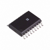
IC TX/RX RS-232 W/EN/SD 18SOIC
Manufacturer
Analog Devices Inc
Type
Transceiverr
Datasheet
1.ADM232AARWZ.pdf
(11 pages)
Specifications of ADM242AR
Rohs Status
RoHS non-compliant
Number Of Drivers/receivers
2/2
Protocol
RS232
Voltage - Supply
4.5 V ~ 5.5 V
Mounting Type
Surface Mount
Package / Case
18-SOIC (7.5mm Width)
Available stocks
Company
Part Number
Manufacturer
Quantity
Price
Company:

Part Number:
ADM242AR
Manufacturer:
AD
Quantity:
5 510
Part Number:
ADM242AR
Manufacturer:
ADI/亚德诺
Quantity:
20 000
Part Number:
ADM242AR-REEL
Manufacturer:
ADI/亚德诺
Quantity:
20 000
Part Number:
ADM242ARZ
Manufacturer:
ADI/亚德诺
Quantity:
20 000


ADM222/ADM232A/ADM242
TTL/CMOS
OUTPUTS
TTL/CMOS
INPUTS
TRANSMITTER
0.1 F
0.1 F
R1
R2
T1
T2
C1
C2
INPUT
OUT
OUT
V
SHDN
OUTPUT
IN
IN
IN
12
11
13
10
3V
0V
6
2
4
5
SHDN
C1+
C1–
C2+
C2–
ADM222
0.1 F
VOLTAGE DOUBLER
VOLTAGE INVERTER
6.3V
V+
C5
V–
+5V TO +10V
+5V TO –10V
16
GND
T2
T1
3k
V
CC
R2
R1
17
t
5V INPUT
ON EACH TTL/CMOS INPUT
ON EACH RS-232 INPUT
DT
INTERNAL 5k
INTERNAL 400k
V–
V+
+ 5V
– 5V
50pF
15
14
18
3
8
7
9
PULL-DOWN RESISTOR
SHDN
T1
T2
R1
R2
PULL-UP RESISTOR
V
C4
0.1 F
OUT
OUT
C3
0.1 F
OUT
IN
IN
RS-232
INPUTS
RS-232
OUTPUTS
Mnemonic
V
V+
V–
GND
C1+
C1–
C2+
C2–
T
T
R
R
NC
EN
SHDN
CC
IN
OUT
IN
OUT
Function
Power Supply Input, 5 V ± 10%.
Internally generated positive supply (+10 V
nominal).
Internally generated negative supply (–10 V
nominal).
Ground Pin. Must be connected to 0 V.
External capacitor 1, (+ terminal) is connected
to this pin.
External capacitor 1, (– terminal) is connected
to this pin.
External capacitor 2, (+ terminal) is connected
to this pin.
External capacitor 2, (– terminal) is connected
to this pin.
Transmitter (Driver) Inputs. These inputs accept
TTL/CMOS levels. An internal 400 kΩ pull-up
resistor to V
Transmitter (Driver) Outputs. These are RS-232
levels (typically ± 9 V).
Receiver Inputs. These inputs accept RS-232
signal levels. An internal 5 kΩ pull-down resistor
to GND is connected on each of these inputs.
Receiver Outputs. These are TTL/CMOS levels.
No Connect. No connections are required to
this pin.
(ADM242 Only) Active Low Digital Input. May
be used to enable or disable (three-state) both
receiver outputs.
(ADM222 and ADM242) Active Low Digital
Input. May be used to disable the device so that
the power consumption is minimized. On the
ADM222 all drivers and receivers are disabled.
On the ADM242 the drivers are disabled but the
receivers remain enabled.
PIN FUNCTION DESCRIPTION
T2
R2
C1+
C1–
C2+
C2–
OUT
NC
V+
V–
IN
NC = NO CONNECT
1
2
3
4
5
6
7
8
9
CC
(Not to Scale)
TOP VIEW
ADM222
is connected on each input.
18
17
16
15
14
13
12
11
10
SHDN
GND
T1
R1
R1
T1
T2
R2
V
CC
OUT
IN
IN
IN
OUT
OUT
B
Related parts for ADM242AR
Image
Part Number
Description
Manufacturer
Datasheet
Request
R

Part Number:
Description:
±1.7g Dual-Axis IMEMS Accelerometer Evaluation Board
Manufacturer:
Analog Devices Inc
Datasheet:

Part Number:
Description:
Inertial Sensor Evaluation System
Manufacturer:
Analog Devices Inc
Datasheet:
Part Number:
Description:
Manufacturer:
Analog Devices Inc
Datasheet:
Part Number:
Description:
Manufacturer:
Analog Devices Inc
Datasheet:
Part Number:
Description:
Manufacturer:
Analog Devices Inc
Datasheet:
Part Number:
Description:
Manufacturer:
Analog Devices Inc
Datasheet:
Part Number:
Description:
Manufacturer:
Analog Devices Inc
Datasheet:
Part Number:
Description:
Manufacturer:
Analog Devices Inc
Datasheet:
Part Number:
Description:
Manufacturer:
Analog Devices Inc
Datasheet:
Part Number:
Description:
Manufacturer:
Analog Devices Inc
Datasheet:
Part Number:
Description:
Manufacturer:
Analog Devices Inc
Datasheet:
Part Number:
Description:
Manufacturer:
Analog Devices Inc
Datasheet:
Part Number:
Description:
Manufacturer:
Analog Devices Inc
Datasheet: