EEEFK1V151P Panasonic, EEEFK1V151P Datasheet
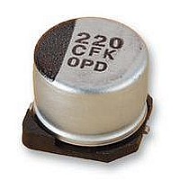
CAPACITOR; ALUMINUM ELECTROLYTIC; ECAP 150UF 35V F CASE FK SMD

EEEFK1V151P

Manufacturer Part Number
EEEFK1V151P
Description
CAPACITOR; ALUMINUM ELECTROLYTIC; ECAP 150UF 35V F CASE FK SMD
Manufacturer
Panasonic
Datasheet

Specifications of EEEFK1V151P

Capacitance
150 μF
Material, Element
Aluminum Electrolytic
Termination
SMT
Voltage, Rating
35 VDC
Capacitance Tolerance
± 20%
Voltage Rating
35V
Life Time @ Temperature
2000 Hours @ 105°C
Height
10.2mm
Diameter
8mm
Capacitor Mounting
SMD
Operating Temperature Range
-55°C To
Rohs Compliant
Yes
Lead Free Status / Rohs Status
RoHS Compliant part

Available stocks

Company
Part Number
Manufacturer
Quantity
Price
Part Number:
EEEFK1V151P
Manufacturer:
PANASONIC
Quantity:
46 000
Surface Mount Type
Series:
● Endurance: 2000 h to 5000 h at 105 °C
● Low impedance (40 % to 60 % less than FC series)
● Vibration-proof product is available upon request. (φ8 <)
● RoHS directive compliant
Design and specifi cations are each subject to change without notice. Ask factory for the current technical specifi cations before purchase and/or use.
Should a safety concern arise regarding this product, please be sure to contact us immediately.
Category Temp. Range
Rated W.V.Range
Nominal Cap.Range
Capacitance Tolerance
DC Leakage Cur rent
tan δ
Characteristics
at Low Temperature
Endurance
Shelf Life
Resistance to
Soldering Heat
Rated Voltage Mark
Example:6.3 V 22 µF, 6.3 V 3300 µF
Marking color : BLACK
< φ10
> φ12.5
Features
Miniaturized (30 % to 50 % less than FC series)
Specifi cations
Marking
Negative polarity
marking (–)
Negative polarity
marking (–)
C
A
E
V
j
Rated Voltage Mark
FK
Rated Voltage Mark
6.3 V
16 V
25 V
35 V
10 V
Type:
Lot number
Lot number
V
Z(–25 °C)/Z(+20 °C)
Z(–40 °C)/Z(+20 °C)
Z(–55 °C)/Z(+20 °C)
After applying rated working voltage for 2000 hours at +105 °C±2 °C and then being stabilized at +20 °C,
Capacitors shall meet the following limits. ( > φ12.5 and suffi x “G” in φ8 10.2, φ10 10.2 are 5000 hours)
Capacitance change
tan δ
DC leakage current
After storage for 1000 hours at +105 °C±2 °C with no voltage applied and then being stabilized
at +20 °C, capacitors shall meet the limits specifi ed in Endurance (With voltage treatment)
After refl ow soldering and then being stabilized at +20 °C, capacitors shall meet the following limits.
Capacitance change
tan δ
DC leakage current
3300
j FK
j FK
22
2A
H
K
J
W.V. (V)
Capacitance (µF)
Series identification
100 V
Capacitance (µF)
Series identification
Mark for Lead-Free
ProductsBlack Dot
(Square)
50 V
63 V
80 V
6.3
2
3
4
I < 0.01 CV or 3 (µA) After 2 minutes (Whichever is greater)
±30 % of initial measured value (Suffi x “G” is 35 %)
< 200 % of initial specifi ed value (Suffi x “G” is 300 %)
< initial specifi ed value
±10 % of initial measured value
< initial specifi ed value
10
2
3
4
Please see the attached standard products list
16
2
3
4
– EE63 –
code
Size
H13
K16
J16
D8
Di men sions in mm (not to scale)
B
C
D
G
E
F
25
±20 % (120 Hz/+20 °C)
2
3
3
10.0
12.5
16.0
18.0
6.3 V.DC to 100 V.DC
4.0
5.0
6.3
6.3
8.0
8.0
D
–55 °C to +105 °C
3.3 µF to 6800 µF
35
2
3
3
10.2±0.3
10.2±0.3
13.5±0.5
16.5±0.5
16.5±0.5
5.8±0.3
5.8±0.3
5.8±0.3
7.7±0.3
6.2±0.3
L
0.3 max.
Aluminum Electrolytic Capacitors/ FK
L
50
2
3
3
10.3
13.5
17.0
19.0
A,B
4.3
5.3
6.6
6.6
8.3
8.3
63
2
3
3
10.0 max.
12.0 max.
15.0 max.
19.0 max.
21.0 max.
5.5 max.
6.5 max.
7.8 max.
7.8 max.
9.5 max.
80
2
3
3
+
H
100
2
3
3
A±0.2
1.8
2.2
2.6
2.6
3.4
3.4
3.5
4.7
5.5
6.7
I
W
(Impedance ratio at 120 Hz)
0.65±0.1
0.65±0.1
0.65±0.1
0.65±0.1
0.65±0.1
0.90±0.2
0.90±0.2
0.90±0.3
1.20±0.3
1.20±0.3
W
( )reference size
1.0
1.5
1.8
1.8
2.2
3.1
4.6
4.4
6.7
6.7
P
00
0.35
0.35
0.35
0.35
0.35
0.70±0.2
0.70±0.2
0.70±0.3
0.70±0.3
0.70±0.3
Sep. 2010
K
+ 1.5
+ 1.5
+ 1.5
+ 1.5
+ 1.5
- 0.2
- 0.2
- 0.2
- 0.2
- 0.2
(mm)

Related parts for EEEFK1V151P

EEEFK1V151P Summary of contents

Page 1

... Z(–55 °C)/Z(+20 °C) After applying rated working voltage for 2000 hours at +105 °C±2 °C and then being stabilized at +20 °C, Capacitors shall meet the following limits. ( > φ12.5 and suffi x “G” in φ8 10.2, φ10 10.2 are 5000 hours) Endurance Capacitance change tan δ ...

Page 2

... Design and specifi cations are each subject to change without notice. Ask factory for the current technical specifi cations before purchase and/or use. Should a safety concern arise regarding this product, please be sure to contact us immediately. Aluminum Electrolytic Capacitors/ FK Specifi cation tan δ ...

Page 3

... Packaging Q'ty Part No. Refl ow (RoHS:compliant) Taping (pcs) EEEFK1V4R7R (1) 2000 EEEFK1V100UR (1) 2000 EEEFK1V100R (1) 1000 EEEFK1V220R (1) 1000 EEEFK1V330P (1) 1000 (1) 1000 EEEFK1V470P EEEFK1V680XP (1) EEEFK1V101XP (1) EEEFK1V101P (2) EEEFK1V151P (2) EEEFK1V221P (2) EEEFK1V331P (2) EEVFK1V471Q (3) EEVFK1V681Q (3) EEVFK1V102M (3) EEVFK1V152M (3) EEEFK1H4R7R (1) 2000 EEEFK1H100UR (1) 1000 EEEFK1H100P (1) 1000 EEEFK1H220P (1) 1000 EEEFK1H330XP (1) EEEFK1H330P (2) 1000 ...

Page 4

... Design and specifi cations are each subject to change without notice. Ask factory for the current technical specifi cations before purchase and/or use. Should a safety concern arise regarding this product, please be sure to contact us immediately. Aluminum Electrolytic Capacitors/ FK Specifi cation tan δ ...

Related keywords