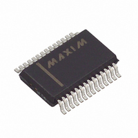
MAX3130EAI+ Maxim Integrated Products, MAX3130EAI+ Datasheet - Page 11

MAX3130EAI+
Manufacturer Part Number
MAX3130EAI+
Description
IC TXRX W/RS232 28-SSOP
Manufacturer
Maxim Integrated Products
Type
Transceiverr
Datasheet
1.MAX3130CAI.pdf
(16 pages)
Specifications of MAX3130EAI+
Number Of Drivers/receivers
2/2
Protocol
RS232
Voltage - Supply
3 V ~ 5 V
Mounting Type
Surface Mount
Package / Case
28-SSOP
Lead Free Status / RoHS Status
Lead free / RoHS Compliant
The infrared transmitter consists of an internal high-
power, open-drain MOSFET switch. This switch has an
on-resistance of less than 2Ω and is capable of switch-
ing 200mA of current. Internal buffering keeps the input
capacitance of the TXD pin extremely low to ease user
drive requirements. Connect an IR LED in series with a
current-setting resistor to select the appropriate IR out-
put power (see the Powering the IR LED section). The
transmitter is not current limited so do not exceed the
power dissipation of the external components during
high duty-cycle transmit schemes.
The TXD input controls the IR LED for the MAX3131.
The T2IN input controls the IR LED for the MAX3130
(IRMODE = low). With the ENDEC disabled (see IrDA
Encoder/Decoder (ENDEC) section), the IR LED is
turned on by a logic-high signal at the TXD or T2IN
input, for the MAX3131 and MAX3130 respectively.
The MAX3130 has the capability to multiplex R2OUT and
T2IN between the IrDA infrared interface and the RS-232
electrical interface. The state of the IRMODE input deter-
mines which interface (infrared or RS-232) is multiplexed
to R2OUT and T2IN. When IRMODE is low, R2OUT acts
as the infrared receiver output and T2IN acts as the
infrared transmitter input. Also, while IRMODE is low, the
RS-232 charge pumps are shut down and the RS-232
transmitters are disabled (see Shutdown section). When
IRMODE is high, R2OUT and T2IN assume their func-
tions as the RS-232 data receive output and transmit
input, respectively. Also, while IRMODE is high, the IR
transmitter is disabled (turned off).
Figure 3a. ENDEC Operation, Receiving Infrared
WITH ENDEC DISABLED
WITH ENDEC ENABLED
PHOTODIODE INPUT *
CS = BAUD16 CLOCK CYCLES
* HIGH = INFRARED LIGHT PULSE
( ) ARE FOR MAX3131
IRMODE : Multiplexed RS-232 Operation
R2OUT (RXD)
R2OUT (RXD)
INFRARED
3V to 5.5V, IrDA Infrared Transceiver with
and IrDA Operation (MAX3130)
______________________________________________________________________________________
1.41 s < t < 3CS
IR Transmitter
16CS
Integrated RS-232 Interface
The MAX3130 has internal edge-detection circuitry that
monitors the RS-232 R2OUT line when IRMODE is low
and monitors the IrDA receive channel when IRMODE
is high. EDGEDET goes low when a positive or negative
edge is detected on either the RS-232 R2OUT line or
the IrDA receive channel (depending on the IRMODE
pin). This edge-detection feature is useful for initiating
an interrupt when data is received on the deselected
line. The EDGEDET signal is cleared when IRMODE is
toggled. Table 1 shows EDGEDET operation.
The MAX3130 and MAX3131 provide an on-board
ENDEC to communicate with UARTs that are not IrDA
compatible. The ENDEC is enabled by applying a clock
with a frequency 16 times the baud rate to the BAUD16
input. This BAUD16 clock is commonly provided on
UARTs that do not have IrDA ENDEC capability. Figure
3 illustrates the operation of the ENDEC. The ENDEC
stretches the incoming infrared pulse (a pulse between
Table 1.
X = Don’t care
* EDGEDET is cleared by any transition on IRMODE.
IRSD
X
X
X
X
RSSD IRMODE
EDGEDET : Edge-Detection Circuitry
X
X
X
X
EDGEDET
IrDA Encoder/Decoder (ENDEC)
16CS
0
0
1
1
Operation
R2IN
X
X
IrDA RxIN
32CS
X
X
(MAX3130)
EDGEDET*
11


