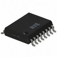
IL41050TE NVE, IL41050TE Datasheet - Page 6

IL41050TE
Manufacturer Part Number
IL41050TE
Description
IC TXRX ISOLATED CAN HS 16SOIC
Manufacturer
NVE
Series
IsoLoop®r
Type
Transceiverr
Datasheet
1.IL41050TE.pdf
(11 pages)
Specifications of IL41050TE
Number Of Drivers/receivers
1/1
Protocol
CAN
Voltage - Supply
3 V ~ 5.5 V
Mounting Type
Surface Mount
Package / Case
16-SOIC (0.300", 7.5mm Width)
Lead Free Status / RoHS Status
Lead free / RoHS Compliant
Other names
390-1131
Available stocks
Company
Part Number
Manufacturer
Quantity
Price
Company:
Part Number:
IL41050TE
Manufacturer:
NVE
Quantity:
100
Application Information
Power Supply Decoupling
Both V
should be placed as close as possible to V
Input Configurations
The TxD input should not be left open as the state will be indeterminate. If connected to an open-drain or open collector output, a pull-up resistor
(typically 16 kΩ) should be connected from the input to V
The Mode Select (“S”) input has a nominal 150 kΩ internal pull-down resistor. It can be left open or set low for normal operation.
Dominant Mode Time-out and Failsafe Receiver Functions
CAN bus latch up is prevented by an integrated Dominant mode timeout function. If the TxD pin is forced permanently low by hardware or
software application failure, the time-out returns the RxD output to the high state no more than 765 μs after TxD is asserted dominant. The timer
is triggered by a negative edge on TxD. If the duration of the low is longer than the internal timer value, the transmitter is disabled, driving the
bus to the recessive state. The timer is reset by a positive edge on pin TxD.
If power is lost on Vdd2, the IL41050 asserts the RxD output high when the supply voltage falls below 3.8 V. RxD will return to normal
operation as soon as Vdd2 rises above approximately 4.2 V.
Programmable Power-Up
A unique non-volatile programmable power-up feature prevents unstable nodes. A state that needs to be present at node power up can be
programmed at the last power down. For example if a CAN node is required to “pulse” dominant at power up, TxD can be sent low by the
controller immediately prior to power down. When power is resumed, the node will immediately go dominant allowing self-check code in the
microcontroller to verify node operation. If desired, the node can also power up silently by presetting the TxD line high at power down. At the
next power on, the IL41050 will remain silent, awaiting a dominant state from the bus.
The microcontroller can check that the CAN node powered down correctly before applying power at the next “power on” request. If the node
powered down as intended, RxD will be set high and stored in IL41050’s non-volatile memory. The level stored in the RxD bit can be read
before isolated node power is enabled, avoiding possible CAN bus disruption due to an unstable node.
Replacing Non-Isolated Transceivers
The IL41050 is designed to replace common non-isolated CAN transceivers such as the Philips/NXP TJA1050 with minimal circuit changes.
Some notable differences:
The VREF Output
V
version. The output is half of the bus supply ±10% (i.e., 0.45 V
IsoRxD / IsoTxD Outputs
The IsoRxD and IsoTxD outputs are isolated versions of the RxD and TxD signals. These outputs are provided on the wide-body version for
troubleshooting, but normally no connections should be made to the pins.
REF
•
•
•
is a reference voltage output used to drive bus threshold comparators in some legacy systems and is provided on the IL41050 wide-body
NVE Corporation
DD1
Some non-isolated CAN transceivers have internal TxD pull-up resistors, but the IL41050 TxD input should not be left open. If
connected to an open-drain or open collector output, a pull-up resistor (typically 16 kΩ) should be connected from the input to V
Initialization behavior varies between CAN transceivers. To ensure the desired power-up state, the IL41050 should be initialized with a
TxD pulse (low-to-high for recessive initialization), or shut down the transceiver in the desired power-up state (the “programmable
power-up feature”).
Many non-isolated CAN transceivers have a V
and V
DD2
must be bypassed with 100 nF ceramic capacitors. These supply the dynamic current required for the isolator switching and
11409 Valley View Road
DD
and their respective ground return pins.
Eden Prairie, MN 55344-3617 USA
REF
DD
1
output. Such a reference is available on the IL41050 wide-body version.
.
DD
2
< V
REF
6
< 0.55 V
Telephone: (952) 829-9217
DD
2
), and can drive up to 50 µA.
Fax (952) 829-9189
Internet: www.isoloop.com
IL41050
DD
1
.


