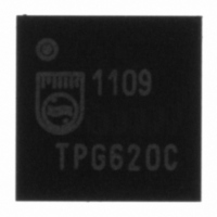
ISP1109BSFE ST-Ericsson Inc, ISP1109BSFE Datasheet - Page 35

ISP1109BSFE
Manufacturer Part Number
ISP1109BSFE
Description
IC TXRX SERIAL BUS UNIV 32HVQFN
Manufacturer
ST-Ericsson Inc
Type
Transceiverr
Datasheet
1.ISP1109BSFE.pdf
(60 pages)
Specifications of ISP1109BSFE
Number Of Drivers/receivers
1/1
Protocol
USB 2.0
Voltage - Supply
3 V ~ 5.25 V
Mounting Type
Surface Mount
Package / Case
32-VQFN Exposed Pad, 32-HVQFN, 32-SQFN, 32-DHVQFN
Lead Free Status / RoHS Status
Lead free / RoHS Compliant
Other names
568-3148
ISP1109BS
ISP1109BS
Available stocks
Company
Part Number
Manufacturer
Quantity
Price
Company:
Part Number:
ISP1109BSFE
Manufacturer:
ST-EricssonInc
Quantity:
1 143
Philips Semiconductors
11. Electro-Static Discharge (ESD)
9397 750 13355
Product data sheet
10.1 Power-down event
10.2 Clock wake-up event
11.1 ESD protection
If V
(0.8 V to 2.0 V), the ISP1109 is in Power-down mode and internal clocks are turned off.
The internal clock—LazyClock or I
set. It takes approximately 8 ms for the clock to stop from the time the Power-down
condition is detected.
If SPI mode is selected, a register read or write access is normal, as when in Power-down
mode. If I
register read or write operation.
The clock wakes up when any of the following events occurs on ISP1109 pins:
The event triggers the clock to start. A stable clock is guaranteed within 100 s.
When an event is triggered and the clock is started, it will remain active for approximately
8 ms. If bit PWR_DN is not cleared within this 8 ms period, the clock will stop. If the clock
wakes up because of any event other than SPI_CLK/I2C_SCL going LOW, an interrupt
will be generated once the clock is active.
The pins that are connected to the USB connector—DP, DM, ID, V
GNDD—have a minimum of 12 kV ESD protection. The 12 kV measurement is limited
by the test equipment. Capacitors of 4.7 F connected from REG3V3 to GNDA and V
to GNDA are required to achieve this 12 kV ESD protection. See
•
•
•
•
•
CC(I/O)
Pin SPI_CLK/I2C_SCL goes LOW, if I
HIGH).
Pin V
bit SESS_VLD_IEH of the Interrupt Enable High register is set.
Status bit ID_FLOAT changes from logic 1 to logic 0, provided bit ID_FLOAT_IEL of
the Interrupt Enable Low register is set.
Status bit ID_FLOAT changes from logic 0 to logic 1, provided bit ID_FLOAT_IEH of
the Interrupt Enable High register is set.
Status bit SE1 changes from logic 0 to logic 1, provided bit SE1_IEH of the Interrupt
Enable High register is set.
2
BUS
is not present and the V
C-bus mode is selected, the internal clock must first be woken up before any
goes above the session valid threshold (0.8 V to 2.0 V), provided
Rev. 01 — 14 July 2005
BUS
2
C-bus clock or both—is stopped when bit PWR_DN is
voltage is below the SESS_VLD threshold
2
C-bus mode is selected (pin SPI_I2C_SEL is
USB transceiver with carkit support
© Koninklijke Philips Electronics N.V. 2005. All rights reserved.
BUS
Figure
, V
ISP1109
CC
12.
, GNDA and
34 of 59
BUS


