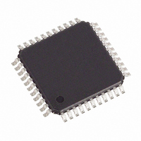
DS2148T+ Maxim Integrated Products, DS2148T+ Datasheet - Page 3

DS2148T+
Manufacturer Part Number
DS2148T+
Description
IC LIU E1/T1/J1 5V 44-TQFP
Manufacturer
Maxim Integrated Products
Type
Line Interface Units (LIUs)r
Specifications of DS2148T+
Number Of Drivers/receivers
1/1
Protocol
T1/E1/J1
Voltage - Supply
4.75 V ~ 5.25 V
Mounting Type
Surface Mount
Package / Case
44-TQFP, 44-VQFP
Lead Free Status / RoHS Status
Lead free / RoHS Compliant
DS2148/DS21Q48
LIST OF FIGURES
Figure 1-1. DS2148 Block Diagram ............................................................................................................7
Figure 1-2. Receive Logic...........................................................................................................................8
Figure 1-3. Transmit Logic..........................................................................................................................9
Figure 2-1. Parallel Port Mode Pinout (BIS1 = 0, BIS0 = 1 or 0) (TQFP Package) ..................................21
Figure 2-2. Serial Port Mode Pinout (BIS1 = 1, BIS0 = 0) (TQFP Package) ............................................21
Figure 2-3. Hardware Mode Pinout (BIS1 = 1, BIS0 = 1) (TQFP Package) .............................................22
Figure 3-1. Serial Port Operation for Read Access (R = 1) Mode 1 .........................................................25
Figure 3-2. Serial Port Operation for Read Access Mode 2 .....................................................................25
Figure 3-3. Serial Port Operation for Read Access Mode 3 .....................................................................26
Figure 3-4. Serial Port Operation for Read Access Mode 4 .....................................................................26
Figure 3-5. Serial Port Operation for Write Access (R = 0) Modes 1 and 2..............................................27
Figure 3-6. Serial Port Operation for Write Access (R = 0) Modes 3 and 4..............................................27
Figure 7-1. Basic Interface .......................................................................................................................49
Figure 7-2. Protected Interface Using Internal Receive Termination........................................................50
Figure 7-3. Protected Interface Using External Receive Termination.......................................................51
Figure 7-4. E1 Transmit Pulse Template ..................................................................................................52
Figure 7-5. T1 Transmit Pulse Template ..................................................................................................53
Figure 7-6. Jitter Tolerance ......................................................................................................................54
Figure 7-7. Jitter Attenuation ....................................................................................................................54
Figure 8-1. 144-Pin CSBGA (17mm x 17mm) Pinout ...............................................................................58
Figure 10-1. Intel Bus Read Timing (PBTS = 0, BIS1 = 0, BIS0 = 0) .......................................................62
Figure 10-2. Intel Bus Write Timing (PBTS = 0, BIS1 = 0, BIS0 = 0) .......................................................62
Figure 10-3. Motorola Bus Timing (PBTS = 1, BIS1 = 0, BIS0 = 0)..........................................................63
Figure 10-4. Intel Bus Read Timing (PBTS = 0, BIS1 = 0, BIS0 = 1) .......................................................65
Figure 10-5. Intel Bus Write Timing (PBTS = 0, BIS1 = 0, BIS0 = 1) .......................................................65
Figure 10-6. Motorola Bus Read Timing (PBTS = 1, BIS1 = 0, BIS0 = 1) ................................................66
Figure 10-7. Motorola Bus Write Timing (PBTS = 1, BIS1 = 0, BIS0 = 1) ................................................66
Figure 10-8. Serial Bus Timing (BIS1 = 1, BIS0 = 0) ................................................................................67
Figure 10-9. Receive Side Timing ............................................................................................................68
Figure 10-10. Transmit Side Timing .........................................................................................................69
3 of 73


