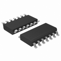
AMIS41682CANM1G ON Semiconductor, AMIS41682CANM1G Datasheet - Page 6

AMIS41682CANM1G
Manufacturer Part Number
AMIS41682CANM1G
Description
TRANSCEIVER CAN 3.3V DGTL 14SOIC
Manufacturer
ON Semiconductor
Type
Transceiverr
Datasheet
1.AMIS41683CANN1G.pdf
(16 pages)
Specifications of AMIS41682CANM1G
Number Of Drivers/receivers
1/1
Protocol
CAN
Voltage - Supply
4.75 V ~ 5.25 V
Mounting Type
Surface Mount
Package / Case
14-SOIC (3.9mm Width), 14-SOL
Operating Supply Voltage
5 V
Supply Current
8 mA
Operating Temperature Range
- 40 C to + 125 C
Mounting Style
SMD/SMT
Product
CAN
Lead Free Status / RoHS Status
Lead free / RoHS Compliant
Other names
766-1016
Available stocks
Company
Part Number
Manufacturer
Quantity
Price
Company:
Part Number:
AMIS41682CANM1G
Manufacturer:
ON Semiconductor
Quantity:
413
Low Power Modes
can be entered and exited via Pins STBB and EN (see
Figure 5). (Go−to−sleep mode is only a transition mode.)
consumption. Pin INH is switched to high−impedance for
deactivation of the external voltage regulator. Pin CANL is
biased to the battery voltage via Pin RTL. If the supply
voltage is provided, Pins RXD and ERR will signal the
wake−up interrupt signal.
The transceiver provides three low power modes, which
The sleep mode is the mode with the lowest power
ERR
ERR
ERR
ERR
ERR
RxD
RxD
RxD
RxD
RxD
TxD
TxD
TxD
TxD
TxD
Failure 1 : CANH wire interrupted
Failure 2 : CANL wire interrupted
Failure 3 : CANH shorted to Vbat
Failure 3a : CANH shorted to Vcc
Failure 5 : CANH shorted to Gnd
Vbat
Vbat
Vbat
Vbat
Vbat
Vcc
Vcc
Vcc
Vcc
Vcc
Error−detection: CL= CH more then 4 pulses
Error−detection: CL= CH more then 4 pulses
RTL
CANL
CANH
RTH
RTL
CANL
CANH
RTH
RTL
CANL
CANH
RTH
RTL
CANL
CANH
RTH
RTL
CANL
CANH
RTH
Error−detection: CL= CH more then 4 pulses
Error−detection: CANH > 2V longer then Tnd_f3
Error−detection: CANH >2V longer then Tnd_f3
Vcc
Vcc
Vbat
GND
Figure 4. Different Types of Wiring Failure
CANH
CANH
CANH
CANH
CANH
CANL
CANL
CANL
CANL
CANL
RTH
RTH
RTH
RTH
RTH
RTL
RTL
RTL
RTL
RTL
0.6Vcc
0.4Vcc
0.6Vcc
0.4Vcc
0.6Vcc
0.4Vcc
0.6Vcc
0.4Vcc
0.6Vcc
0.4Vcc
CD
CD
CD
CD
CD
CL
CL
CL
CL
CL
CH
CH
CH
CH
CH
http://onsemi.com
TxD
RxD
ERR
TxD
RxD
ERR
TxD
RxD
ERR
TxD
RxD
ERR
TxD
RxD
ERR
6
but with a high−level on pin INH.
mode with the battery power−on flag instead of the wake−up
interrupt signal on Pin ERR. The output on Pin RXD will
show the wake−up interrupt. This mode is only for reading
out the power−on flag.
ERR
ERR
ERR
ERR
RxD
RxD
RxD
RxD
TxD
TxD
TxD
TxD
The standby mode will react the same as the sleep mode
The power−on standby mode is the same as the standby
Wake−up request is detected by the following events:
Failure 4 : CANL shorted to Gnd
Failure 6 : CANL wire shorted to Vbat
Failure 6a : CANL shorted to Vcc
Failure 7 : CANH shorted to CANL
Vbat
Vbat
Vbat
Vbat
Vcc
Vcc
Vcc
Vcc
RTL
CANL
CANH
RTH
RTL
CANL
CANH
RTH
RTL
CANL
CANH
RTH
RTL
CANL
CANH
RTH
Error−detection: CL= CH more then 4 pulses
Error−detection: dominant longer then Tnd_f7
Error−detection: dominant longer then Tnd_f4
Error−detection: CANL>7V
Vbat
GND
Vcc
CANH
CANH
CANH
CANH
CANL
CANL
CANL
CANL
RTH
RTH
RTH
RTH
RTL
RTL
RTL
RTL
0.6Vcc
0.4Vcc
0.6Vcc
0.4Vcc
0.6Vcc
0.4Vcc
0.6Vcc
0.4Vcc
CD
CD
CD
CD
CL
CL
CL
CL
CH
CH
CH
CH
TxD
RxD
ERR
TxD
RxD
ERR
TxD
RxD
ERR
TxD
RxD
ERR


