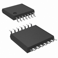
DS90LV019TMTC/NOPB National Semiconductor, DS90LV019TMTC/NOPB Datasheet

DS90LV019TMTC/NOPB
Specifications of DS90LV019TMTC/NOPB
DS90LV019TMTC
Related parts for DS90LV019TMTC/NOPB
DS90LV019TMTC/NOPB Summary of contents
Page 1
... Connection Diagram Block Diagram TRI-STATE ® registered trademark of National Semiconductor Corporation. © 2000 National Semiconductor Corporation Features n LVDS Signaling n 3.3V or 5.0V operation n Low power CMOS design n Balanced Output Impedance ...
Page 2
... Absolute Maximum Ratings If Military/Aerospace specified devices are required, please contact the National Semiconductor Sales Office/ Distributors for availability and specifications. Supply Voltage V CC Enable Input Voltage (DE, RE) Driver Input Voltage ( Receiver Output Voltage (R ) OUT ± Driver Output Voltage (DO ) ± Receiver Input Voltage (RI ...
Page 3
DC Electrical Characteristics T = −40˚C to +85˚C unless otherwise noted Symbol Parameter DIFFERENTIAL DRIVER CHARACTERISTICS V Output Differential Voltage Magnitude Change Offset Voltage OS V Offset Magnitude Change OS I TRI-STATE ...
Page 4
AC Electrical Characteristics ± −40˚C to +85˚ 3. Symbol Parameter DRIVER TIMING REQUIREMENTS t Disable Time High to Z PHZ t Disable Time Low to Z PLZ t Enable Time Z to High PZH ...
Page 5
Test Circuits and Timing Waveforms FIGURE 2. Differential Driver Propagation Delay and Transition Test Circuit FIGURE 3. Differential Driver Propagation and Transition Time Waveforms FIGURE 1. Differential Driver DC Test Circuit FIGURE 4. Driver TRI-STATE Delay Test Circuit 5 DS100053-3 ...
Page 6
Test Circuits and Timing Waveforms FIGURE 6. Receiver Propagation Delay and Transition Time Test Circuit FIGURE 7. Receiver Propagation Delay and Transition Time Waveforms www.national.com (Continued) FIGURE 5. Driver TRI-STATE Delay Waveforms FIGURE 8. Receiver TRI-STATE Delay Test Circuit 6 ...
Page 7
Test Circuits and Timing Waveforms FIGURE 9. Receiver TRI-STATE Delay Waveforms TRI-STATE Delay Waveforms Typical Application Diagram Applications Information The DS90LV019 has two control pins, which allows the de- vice to operate as a driver, a receiver or both driver ...
Page 8
Applications Information • Balanced cables (e.g., twisted pair) are usually better than unbalanced cables (ribbon cable, simple coax) for noise reduction and signal quality. < • For cable distances 0.5m, most cables can be made to work effectively. For distances ...
Page 9
Physical Dimensions inches (millimeters) unless otherwise noted Order Number DS90LV019TM NS Package Number M14A 9 www.national.com ...
Page 10
... NATIONAL’S PRODUCTS ARE NOT AUTHORIZED FOR USE AS CRITICAL COMPONENTS IN LIFE SUPPORT DEVICES OR SYSTEMS WITHOUT THE EXPRESS WRITTEN APPROVAL OF THE PRESIDENT AND GENERAL COUNSEL OF NATIONAL SEMICONDUCTOR CORPORATION. As used herein: 1. Life support devices or systems are devices or systems which, (a) are intended for surgical implant ...


