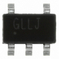
ISL3280EFHZ-T Intersil, ISL3280EFHZ-T Datasheet - Page 7

ISL3280EFHZ-T
Manufacturer Part Number
ISL3280EFHZ-T
Description
IC RCVR ESD RS485/422 LP SOT23-5
Manufacturer
Intersil
Type
Receiverr
Datasheet
1.ISL3283EIHZ-T.pdf
(15 pages)
Specifications of ISL3280EFHZ-T
Number Of Drivers/receivers
0/1
Protocol
RS422, RS485
Voltage - Supply
3 V ~ 5.5 V
Mounting Type
Surface Mount
Package / Case
SOT-23-5, SC-74A, SOT-25
Lead Free Status / RoHS Status
Lead free / RoHS Compliant
Other names
ISL3280EFHZ-TTR
Electrical Specifications
NOTES:
10. Parts are 100% tested at +25°C. Over-temperature limits established by characterization and are not production tested.
11. Typical values are at 3.3V, 5V. Parameters with a single entry in the “TYP” column apply to 3.3V and 5V.
Receiver Output Low Voltage
Three-State (high impedance)
Receiver Output Current
(Notes 8, 9)
SUPPLY CURRENT
No-Load Supply Current
Shutdown Supply Current
(Note 8)
ESD PERFORMANCE
RS-485 Pins (A, B)
All Pins
RECEIVER SWITCHING CHARACTERISTICS
Maximum Data Rate
Receiver Input to Output Delay t
Receiver Skew | t
Receiver Enable to Output
High (Note 8)
Receiver Enable to Output
Low (Note 8)
Receiver Disable from Output
High (Note 8)
Receiver Disable from Output
Low (Note 8)
7. All currents into device pins are positive; all currents out of device pins are negative. All voltages are referenced to device ground unless otherwise
8. Does not apply to the ISL3280E or ISL3284E.
9. If the Rx enable function isn’t needed, connect the enable pin to the appropriate supply, as described in the “Pin Descriptions” table.
specified.
PARAMETER
PLH
- t
ISL3280E, ISL3281E, ISL3282E, ISL3283E, ISL3284E, ISL3285E
PHL
|
SYMBOL
PLH
7
Test Conditions: V
T
I
V
V
V
V
SHDN
I
f
t
t
t
t
A
OZR
I
MAX
SK1
SK2
SK3
SK4
t
t
t
t
OL1
OL2
OL3
OL4
CC
ZH
HZ
ZL
LZ
, t
= +25°C (Note 11); Unless Otherwise Specified (Note 7). (Continued)
PHL
I
ISL3284E, ISL3285E
I
I
I
0V ≤ V
RE/RE = V
RE/RE = 0V/V
IEC61000-4-2, Air-Gap Discharge Method
IEC61000-4-2, Contact Discharge Method
Human Body Model, From Bus Pins to GND
HBM, per MIL-STD-883 Method 3015
MM
V
(Note 11)
V
V
V
V
V
V
R
SW = GND (Figure 2)
R
SW = V
R
SW = GND (Figure 2)
R
SW = V
O
O
O
O
ID
ID
L ≥
CC
CC
L ≥
L
L
L
L
L
= 1mA, V
= 500µA, V
= 4mA, V
= 2mA, V
= 1.5V (Figure 1)
= 1kΩ, C
= 1kΩ, C
= 1kΩ, C
= 1kΩ, C
= ±2V, V
= ±2V, V
1.5V (Figure 1)
= 3.3V ±10% (Figure 1) V
1.8V (Figure 1)
= 5V ±10% (Figure 1)
O
CC
CC
CC
≤ V
CC
= 3.0V to 5.5V; V
(Figure 2)
(Figure 2)
L ≥
ID
L ≥
L
L
L
L
CC
CM
CM
L ≥
/0V
= 15pF,
= 15pF,
= 15pF,
= 15pF,
CC
TEST CONDITIONS
= -200mV, V
1.35V
1.5V
= 0V (Figure 1 and Table 2)
= 0V (Figure 1)
1.35V
L ≥
L
= V
ISL3282E,
ISL3284E, and
ISL3285E Only
ISL3282E,
ISL3284E, and
ISL3285E Only
ISL3282E,
ISL3284E, or
ISL3285E
ISL3282E,
ISL3284E, and
ISL3285E Only
Note 11
V
Note 11
V
V
V
2.2V if ISL3282E,
L
L ≥
L ≥
L ≥
L ≥
= V
CC
1.5V, Note 11
1.5V, Note 11
1.5V, Note 11
1.5V, Note 11
CC
(ISL3282E, ISL3284E, ISL3285E only); Typicals are at
if
TEMP
(°C)
Full
Full
Full
Full
Full
Full
Full
Full
Full
Full
Full
Full
Full
Full
25
25
25
25
25
25
25
25
25
25
25
25
25
(Note 10)
MIN
20
20
-1
-
-
-
-
-
-
-
-
-
-
-
-
-
-
-
-
-
-
-
-
-
-
-
-
(Note 11)
250, 120
250, 120
240, 90
240, 90
30, 24
24, 20
24, 20
0.015
±16.5
±16.5
±250
TYP
400
0.2
0.2
0.1
0.1
±9
±5
36
44
10
10
1
2
2
4
-
(Note 10) UNITS
MAX
500
500
500
0.4
0.4
0.4
5.5
7.5
20
60
20
20
1
-
-
-
-
-
-
-
-
-
-
-
-
-
-
October 18, 2007
FN6543.2
Mbps
µA
µA
µA
kV
kV
kV
kV
ns
ns
ns
ns
ns
ns
ns
ns
ns
ns
ns
ns
ns
ns
V
V
V
V
V


