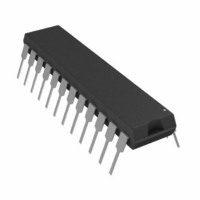
ADM238LJNZ Analog Devices Inc, ADM238LJNZ Datasheet - Page 7

ADM238LJNZ
Manufacturer Part Number
ADM238LJNZ
Description
IC TX/RX QUAD RS-232 5VLP 24DIP
Manufacturer
Analog Devices Inc
Type
Transceiverr
Datasheet
1.ADM238LJNZ.pdf
(20 pages)
Specifications of ADM238LJNZ
Number Of Drivers/receivers
4/4
Protocol
RS232
Voltage - Supply
4.75 V ~ 5.25 V
Mounting Type
Through Hole
Package / Case
24-DIP (0.300", 7.62mm)
Device Type
Transceiver
Ic Interface Type
RS232
No. Of Drivers
4
Supply Voltage Range
4.5V To 5.5V
Driver Case Style
DIP
No. Of Pins
24
Operating Temperature Range
-40°C To +85°C
Data Rate
120Kbps
Interface Circuit Standard 1
RS-232
Number Of Receivers
4
Number Of Transmitters
4
Number Of Transceivers
1
Data Transmission Topology
Point-to-Point
Receiver Signal Type
Single-Ended
Transmitter Signal Type
Single-Ended
Single Supply Voltage (typ)
5V
Single Supply Voltage (min)
4.5V
Single Supply Voltage (max)
5.5V
Dual Supply Voltage (typ)
Not RequiredV
Dual Supply Voltage (min)
Not RequiredV
Dual Supply Voltage (max)
Not RequiredV
Supply Current
13mA
Power Supply Requirement
Single
Operating Temp Range
0C to 70C
Operating Temperature Classification
Commercial
Mounting
Through Hole
Pin Count
24
Package Type
PDIP
Lead Free Status / RoHS Status
Lead free / RoHS Compliant
Lead Free Status / RoHS Status
Lead free / RoHS Compliant, Lead free / RoHS Compliant
Table 4. Pin Function Descriptions
Mnemonic
V
V+
V−
GND
C+
C−
C1+
C1−
C2+
C2−
T
T
R
R
EN
SD
NC
Table 5. ADM236L and ADM241L Truth Table
SD
0
0
1
IN
OUT
CC
IN
OUT
Function
Power Supply Input. 5 V ± 10% (5 V ± 5% for ADM233L).
Internally Generated Positive Supply (+10 V nominal) on all parts, except ADM231L and ADM239L. ADM231L and ADM239L
require an external 7.5 V to 13.2 V supply.
Internally Generated Negative Supply (−10 V nominal).
Ground Pin. Must be connected to 0 V.
(ADM231L and ADM239L only) External capacitor (+ terminal) is connected to this pin.
(ADM231L and ADM239L only) External capacitor (– terminal) is connected to this pin.
(ADM232L, ADM234L, ADM236L, ADM237L, ADM238L, and ADM241L) External capacitor (+ terminal) is connected to this
pin. (ADM233L) The capacitor is connected internally and no external connection to this pin is required.
(ADM232L, ADM234L, ADM236L, ADM237L, ADM238L, and ADM241L) External capacitor (− terminal) is connected to this
pin. (ADM233L) The capacitor is connected internally and no external connection to this pin is required.
(ADM232L, ADM234L, ADM236L, ADM237L, ADM238L, and ADM241L) External capacitor (+ terminal) is connected to this
pin. (ADM233L) Internal capacitor connections, Pin 11 and Pin 15, must be connected together.
(ADM232L, ADM234L, ADM236L, ADM237L, ADM238L, and ADM241L) External capacitor (− terminal) is connected to this
pin. (ADM233L) Internal capacitor connections, Pin 10 and Pin 16, must be connected together.
Transmitter (Driver) Inputs. These inputs accept TTL/CMOS levels. An internal 400 kΩ pull-up resistor to V
each input.
Transmitter (Driver) Outputs. These are RS-232 levels (typically ±10 V).
Receiver Inputs. These inputs accept RS-232 signal levels. An internal 5 kΩ pull-down resistor to GND is connected on each input.
Receiver Outputs. These are TTL/CMOS levels.
Enable Input. Active low on ADM236L, ADM239L, and ADM241L. This input is used to enable/disable the receiver outputs.
With EN = low, the receiver outputs are enabled. With EN = high, the outputs are placed in a high impedance state. This
facility is useful for connecting to microprocessor systems.
Shutdown Input. Active high on ADM236L and ADM241L. With SD = high on the ADM236L and ADM241L, the charge pump
is disabled, the receiver outputs are placed in a high impedance state, and the driver outputs are turned off.
No Connect. No connections are required to this pin.
EN
0
1
0
Status
Normal Operation
Normal Operation
Shutdown
Rev. C | Page 7 of 20
Transmitters T1 to T5
Enabled
Enabled
Disabled
ADM231L–ADM234L/ADM236L–ADM241L
Receivers R1 to R5
Enabled
Disabled
Disabled
CC
is connected to


