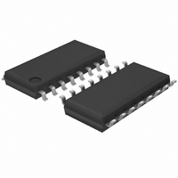
BU2090F-E2 Rohm Semiconductor, BU2090F-E2 Datasheet

BU2090F-E2
Specifications of BU2090F-E2
BU2090F-E2TR
Available stocks
Related parts for BU2090F-E2
BU2090F-E2 Summary of contents
Page 1
... TECHNICAL NOTE Serial-in / Parallel-out Driver Series Serial / Parallel 2-input Drivers BU2098F, BU2090F, BU2090FS ●Description Serial-in-parallel-out driver is a open drain output driver. It incorporates a built-in shift register and a latch circuit to turn on a maximum of 12 LED by a 2-line interface, linked to a microcontroller. A open drain output provides maximum of 25mA current. ...
Page 2
... Input Low-level voltage Output Low-level voltage Input Low-level current Input High-level current Output leakage current Static dissipation current BU2090F/FS (unless otherwise noted, V Parameter Input High-level voltage Input Low-level voltage Output Low-level voltage “H” output disable current “L” output disable current Static dissipation current ● ...
Page 3
... BU2098F PIN No. Pin Name I N.C. 14 SCL 15 SDA I BU2090F/FS PIN No. Pin Name I DATA 3 CLOCK Q10 15 Q11 Address input, internally pull- Open drain output - GND O Open drain output - Non connected I Serial clock input Serial data input/output - Power supply - GND I Serial data input ...
Page 4
... I C BUS A0 Controller A1 A2 BU2090F/FS CLOCK Controller DATA ●Interfaces BU2090F/FS DATA, CLOCK GND (V ) GND (V SS BU2098F A0~ GND (V ) GND (V ) GND ( Shift Register Shift Register BU2090F/FS Q0~Q11 GND ( BU2098F SDA GND (V ) GND (V ) GND ( 4/ Write t 8bit c Buffer Write t 12bit c Buffer h BU2098F Q0~Q7 OUT ...
Page 5
V Parameter SCL clock frequency Bus free time between start-stop condition Hold time start condition Low period of the SCL clock High period of the SCL clock Set up time Re-start condition Data hold ...
Page 6
The start condition is a “HIGH” to “LOW” transition of the SDA line while SCL is “HIGH”. ○Stop condition The stop condition is a “LOW” to “HIGH” transition of the SDA line while SCL is “HIGH”. SDA ...
Page 7
DATA Send the stave address from master following the start condition (S). This address consists of 7 bits. The left 1 bit (the foot bit) is fixed “0”. The stop condition (P) is needed to finish the data transferred. ...
Page 8
SDA Slave address Latch pulse Output (Q7~Q0) Command sample for driving LEDs. These are all off. (terminal A0~A2 is open) SDA Slave address ・RESET CONDITION After reset, ...
Page 9
... V Parameter Minimum clock frequency Data shift set up time Data shift hold time Data latch set up time Data latch hold time Data latch ”L” set up time Data latch ”L” hold time ●Switching time test circuit ● ...
Page 10
... Slave address Device code SCL Start condition SDA 【BU2090F/FS】 CLOCK DATA D11 D10 Q11 Q10 External terminal ACK Note) Diagram shows a status where a pull-up resistor is connected to output Note1) Note2) Output terminal is provided with a pull-up resistor. 10/12 ...
Page 11
Notes 1. Absolute maximum ratings An excess in the absolute maximum ratings, such as supply voltage, temperature range of operating conditions, etc., can break down the devices, thus making impossible to identify breaking mode, such as a short circuit ...
Page 12
Designations (Selections) for Ordering ROHM model name BU SOP16 <Dimension> 10.0±0 1.27 0.4±0.1 SSOP-A16 <Dimension> 6.6±0 0.15±0.1 0.1 0.8 0.36±0 Product number Package type F ...
Page 13
Appendix No technical content pages of this document may be reproduced in any form or transmitted by any means without prior permission of ROHM CO.,LTD. The contents described herein are subject to change without notice. The specifications for the product ...


