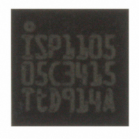
ISP1105WTS ST-Ericsson Inc, ISP1105WTS Datasheet - Page 8

ISP1105WTS
Manufacturer Part Number
ISP1105WTS
Description
IC USB TRANSCEIVER 16-HBCC
Manufacturer
ST-Ericsson Inc
Type
Transceiverr
Datasheet
1.ISP1105BSTM.pdf
(29 pages)
Specifications of ISP1105WTS
Number Of Drivers/receivers
1/1
Protocol
USB 2.0
Voltage - Supply
4 V ~ 5.5 V
Mounting Type
Surface Mount
Package / Case
16-HBCC
Lead Free Status / RoHS Status
Lead free / RoHS Compliant
Other names
568-3145-2
ISP1105W-G
ISP1105W-G
Available stocks
Company
Part Number
Manufacturer
Quantity
Price
Part Number:
ISP1105WTS
Manufacturer:
ST
Quantity:
20 000
Philips Semiconductors
7. Functional description
9397 750 11231
Product data
7.1 Function selection
7.2 Operating functions
Table 4:
[1]
[2]
[3]
Table 5:
Table 6:
Table 7:
[1]
[2]
SUSPND OE
L
L
H
H
FSE0
L
L
H
H
VMO
L
L
H
H
(D , D )
Differential logic 0
Differential logic 1
SE0
Signal levels on (D , D
In ‘suspend’ mode (SUSPND = HIGH) the differential receiver is inactive and output RCV is always
LOW. Out-of-suspend (‘K’) signalling is detected via the single-ended receivers VP and VM.
During suspend, the slew-rate control circuit of low-speed operation is disabled. The (D , D
are still driven to their intended states, without slew-rate control. This is permitted because driving
during suspend is used to signal remote wake-up by driving a ‘K’ signal (one transition from idle to
‘K’ state) for a period of 1 to 15 ms.
VP = VM = H indicates the sharing mode (V
RCV* denotes the signal level on output RCV just before SE0 state occurs. This level is stable during
the SE0 period.
L
H
L
H
Function table
Driving function (pin OE = L) using single-ended input data interface for
ISP1105 (pin MODE = L)
Driving function (pin OE = L) using differential input data interface for
ISP1105 (pin MODE = H) and ISP1106
Receiving function (pin OE = H)
Rev. 08 — 19 February 2004
VO
L
H
L
H
VPO
L
H
L
H
(D , D )
driving and
receiving
receiving
driving
high-Z
are determined by other USB devices and external pull-up/down resistors.
[1]
[1]
RCV
active
active
inactive
inactive
Data
differential logic 0
differential logic 1
SE0
SE0
Data
SE0
differential logic 1
differential logic 0
illegal state
RCV
L
H
RCV*
CC(5.0)
[2]
[2]
[2]
and V
VP/VM
active
active
active
active
reg(3.3)
VP
L
H
L
© Koninklijke Philips Electronics N.V. 2004. All rights reserved.
[1]
are disconnected).
Advanced USB transceivers
ISP1105/1106
Function
normal driving
(differential receiver active)
receiving
driving during ‘suspend’
(differential receiver inactive)
low-power state
VM
H
L
L
[1]
[3]
lines
7 of 28


