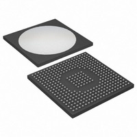
DS3148N Maxim Integrated Products, DS3148N Datasheet - Page 30

DS3148N
Manufacturer Part Number
DS3148N
Description
IC 8CH DS3/3 FRAMER 349-BGA
Manufacturer
Maxim Integrated Products
Datasheet
1.DS3148.pdf
(89 pages)
Specifications of DS3148N
Controller Type
DS3/E3 Framer
Interface
LIU
Voltage - Supply
3.135 V ~ 3.465 V
Current - Supply
640mA
Operating Temperature
-40°C ~ 85°C
Mounting Type
Surface Mount
Package / Case
349-BGA
Lead Free Status / RoHS Status
Lead free / RoHS Compliant
Available stocks
Company
Part Number
Manufacturer
Quantity
Price
Register Name:
Register Description:
Register Address:
Bit #
Name
Default
Note: See
Bit 0: One-Second Timer Latched (OSTL). This latched status bit is set to 1 on each 1-second boundary, as
timed by the device. The device chooses an arbitrary 1-second boundary that is timed from either the RCLK signal
or the TICLK signal depending on the setting of the OSTCS bit in MC2. OSTL is cleared when the host processor
writes a 1 to it and is not set again until another 1-second boundary has occurred. When OSTL is set, it can cause
a hardware interrupt to occur if the OSTIE bit in the
is cleared or the interrupt-enable bit is cleared. This bit can be used to determine when to read the error counters, if
the counters are automatically updated by the 1-second timer.
Bit 1: Counter Overflow Event Latched (COVFL). This latched status bit is set to 1 when the COVF status bit in
the
COVF goes high again. When COVFL is set, it can cause a hardware interrupt to occur if the COVFIE bit in the
MSRIE
bit can be used to determine when a counter overflow event occurs.
Bit 6: Loss-of-Transmit Clock Latched (LOTCL). This latched status bit is set to 1 when the LOTC status bit in
the
LOTC goes high again. When LOTCL is set, it can cause a hardware interrupt to occur if the LOTCIE bit in the
MSRIE
bit can be used to determine when a loss of transmit clock event occurs.
Bit 7: Loss-of-Receive Clock Latched (LORCL). This latched status bit is set to 1 when the LORC status bit in
the
LORC goes high again. When LORCL is set, it can cause a hardware interrupt to occur if the LORCIE bit in the
MSRIE
bit can be used to determine when a loss of receive clock event occurs.
MSR
MSR
MSR
register is set to 1. The interrupt is cleared when this bit is cleared or the interrupt-enable bit is cleared. This
register is set to 1. The interrupt is cleared when this bit is cleared or the interrupt-enable bit is cleared. This
register is set to 1. The interrupt is cleared when this bit is cleared or the interrupt-enable bit is cleared. This
Figure 7-4
register goes high. COVFL is cleared when the host processor writes a 1 to it and is not set again until
register goes high. LOTCL is cleared when the host processor writes a 1 to it and is not set again until
register goes high. LORCL is cleared when the host processor writes a 1 to it and is not set again until
LORCL
—
7
for details on the interrupt logic for the status bits in the MSRL register.
LOTCL
—
6
MSRL
Master Status Register Latched
09h
N/A
—
5
MSRIE
30 of 89
N/A
—
4
register is set to 1. The interrupt is cleared when this bit
N/A
—
3
N/A
—
2
COVFL
—
1
OSTL
—
0


