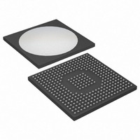
DS3148 Maxim Integrated Products, DS3148 Datasheet - Page 23

DS3148
Manufacturer Part Number
DS3148
Description
IC 8CH DS3/3 FRAMER 349-BGA
Manufacturer
Maxim Integrated Products
Datasheet
1.DS3148.pdf
(89 pages)
Specifications of DS3148
Controller Type
DS3/E3 Framer
Interface
LIU
Voltage - Supply
3.135 V ~ 3.465 V
Current - Supply
640mA
Operating Temperature
-40°C ~ 85°C
Mounting Type
Surface Mount
Package / Case
349-BGA
Lead Free Status / RoHS Status
Lead free / RoHS Compliant
Available stocks
Company
Part Number
Manufacturer
Quantity
Price
Part Number:
DS3148
Manufacturer:
DALLAS
Quantity:
20 000
Bit 3: Automatic Error-Counters Update Defeat (AECU). When this bit is logic 0, the device automatically
updates the DS3/E3 performance error counters on an internally created 1-second boundary based on the RCLK
or TCLK signal, depending on the OSTCS control bit. The host processor is notified of the update through the
setting of the OST status bit in the
retrieve the error count information before it is overwritten with the next update. When this bit is set high, the device
disables the automatic 1-second update and enables a manual update mode. In the manual update mode, the
device relies on either the RECU hardware input signal or the MECU control bit to update the error counters. The
RECU hardware input signal and MECU control bit are logically ORed and therefore a 0-to-1 transition on either
initiates an error counter update. After either the RECU signal or MECU bit has toggled, the host processor must
wait at least 100ns before reading the error counters to allow the device time to complete the update.
Bit 4: Manual Error-Counter Update (MECU). A 0-to-1 transition on this bit causes the device to update the
performance error counters. This bit is ignored if the AECU control bit is logic 0. This bit must be cleared and set
again for a subsequent update. This bit is logically ORed with the RECU input pin.
Bit 5: DS3/E3 POS/NEG Binary Mode Select (BIN). Selects the mode of the LIU interface signals.
Bit 6: Zero Code Suppression Disable (ZCSD). When BIN = 1, zero code suppression is automatically disabled
and ZCSD has no effect.
Bit 7: Loss-of-Transmit Clock Mux Control (LOTCMC). The device can detect if the TICLK fails to transition. If
this bit is logic 0, the device takes no action (other than setting the LOTC status bit) when the TICLK fails to
transition. If this bit is logic 1, when TICLK fails to transition the device automatically switches the transmitter to the
input receive clock (RCLK) and transmits AIS.
0 = enable the automatic update mode and disable the manual update mode
1 = disable the automatic update mode and enable the manual update mode
0 = dual rail mode (data on TPOS/TNEG and RPOS/RNEG)
1 = binary NRZ mode (data on TNRZ and RNRZ with line-code violation pulses on RLCV)
0 = enable the B3ZS/HDB3 encoder and decoder; coding is AMI with zero substitution
1 = disable the B3ZS/HDB3 encoder and decoder; coding is AMI without zero substitution
0 = do not switch the transmitter to RCLK if TICLK fails to transition
1 = automatically switch the transmitter to RCLK and transmit AIS if TICLK fails to transition
MSRL
register. In this mode, the host processor has a full 1-second period to
23 of 89


