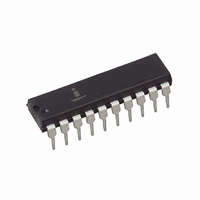
CP82C89Z Intersil, CP82C89Z Datasheet

CP82C89Z
Specifications of CP82C89Z
Available stocks
Related parts for CP82C89Z
CP82C89Z Summary of contents
Page 1
... NUMBER MARKING RANGE (°C) CP82C89 CP82C89 0 to +70 CP82C89Z* CP82C89Z 0 to +70 (Note) MD82C89/B MD82C89/B -55 to +125 20 Ld CERDIP F20.3 NOTE: Intersil Pb-free plus anneal products employ special Pb-free material sets; molding compounds/die attach materials and 100% matte tin plate termination finish, which are RoHS compliant and compatible with both SnPb and Pb-free soldering operations ...
Page 2
Functional Diagram S 2 80C86 80C88 STATUS S 0 LOCK CLK CONTROL/ CRQLCK STRAPPING RESB OPTIONS ANYRQST IOB Pin Description PIN SYMBOL NUMBER TYPE The +5V Power supply pin. A 0.1µF capacitor between pins ...
Page 3
Pin Description (Continued) PIN SYMBOL NUMBER TYPE SYSB/RESB 3 I SYSTEM BUS/RESIDENT BUS: An input signal when the arbiter is configured in the System/Resident Mode (RESB is strapped high) which determines when the multi-master system bus is requested and multi-master ...
Page 4
Priority Resolving Techniques Since there can be many bus masters on a multi-master system bus, some means of resolving priority between bus masters simultaneously requesting the bus must be provided. The 82C89 Bus Arbiter provides several resolving techniques. All the ...
Page 5
Which Priority Resolving Technique To Use There are advantages and disadvantages for each of the techniques described above. The rotating priority resolving technique requires substantial external logic to implement while the serial technique uses no external logic but can accommodate ...
Page 6
RDY2 82C84A/85 CLOCK GENERATOR AEN2 RDY1 READY AEN1 CLK READY CLK 80C86 CPU S0 S1 AD0-AD15 STATUS (S0, S1, S2) A16-A19 S2 OE ADDRESS PROCESSOR LATCH LOCAL BUS 82C82/ 82C83H ( TRANSCEIVER 82C86H/ 82C87H ...
Page 7
XACK(I/O BUS) READY 8089 IOP AD0-AD15 A16-A19 I/O COMMAND BUS PROCESSOR LOCAL BUS OE STB ADDRESS I/O LATCH ADDRESS 82C82/ BUS 82C83H ( I/O TRANSCEIVER DATA 82C86H/ BUS 82C87H (2) FIGURE 5. TYPICAL MEDIUM COMPLEXITY IOB ...
Page 8
XACK RESIDENT BUS RESIDENT COMMAND BUS PROM OR DECODER OR CMOS HPL (NOTE) RESIDENT ADDRESS BUS RESIDENT DATA BUS FIGURE 6. 82C89 BUS ARBITER SHOWN IN SYSTEM - RESIDENT BUS CONFIGURATION NOTE: By adding another 82C89 arbiter and connecting its ...
Page 9
TABLE 1. SUMMARY OF 82C89 MODES, REQUESTING AND RELINQUISHING THE MULTI-MASTER SYSTEM BUS SINGLE LINES FROM IOB MODE 80C86 OR 80C88 OR 8088 ONLY IOB = LOW RESB = LOW I Commands 0 0 ...
Page 10
Absolute Maximum Ratings Supply Voltage . . . . . . . . . . . . . . . . . . . . . . . . . . . . . . . . . . . ...
Page 11
AC Electrical Specifications SYMBOL PARAMETER TCLCL CLK Cycle Period (1) TCLCH CLK Low Time (2) TCHCL CLK High Time (3) TSVCH Status Active Setup (4) TSHCL Status Inactive Setup (5) THVCH Status Inactive Hold ...
Page 12
AC Test Load Circuits BUSY, CBRQ LOAD CIRCUIT 2.5V 102Ω OUTPUT FROM TEST DEVICE POINT UNDER TEST 100pF (NOTE) NOTE: Includes Stray and Jig Capacitance AC Testing Input, Output Waveform INPUT V +0.4V IH 1.5V V -0.4V IL Burn-In Circuits ...
Page 13
... Accordingly, the reader is cautioned to verify that data sheets are current before placing orders. Information furnished by Intersil is believed to be accurate and reliable. However, no responsibility is assumed by Intersil or its subsidiaries for its use; nor for any infringements of patents or other rights of third parties which may result from its use ...


