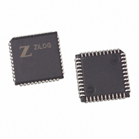
Z8023016VSC Zilog, Z8023016VSC Datasheet - Page 38

Z8023016VSC
Manufacturer Part Number
Z8023016VSC
Description
IC 16MHZ Z8000 CMOS ESCC 44-PLCC
Manufacturer
Zilog
Series
IUSC™r
Datasheet
1.Z8523L10VEG.pdf
(118 pages)
Specifications of Z8023016VSC
Controller Type
Serial Communications Controller (SCC)
Interface
Bus
Voltage - Supply
4.5 V ~ 5.5 V
Current - Supply
7mA
Operating Temperature
0°C ~ 70°C
Mounting Type
Surface Mount
Package / Case
44-LCC (J-Lead)
Lead Free Status / RoHS Status
Contains lead / RoHS non-compliant
Available stocks
Company
Part Number
Manufacturer
Quantity
Price
Table 5. Z80230 Register Map (Shift Left Mode)
PS005308-0609
AD5
0
0
0
0
0
0
0
0
0
0
0
0
AD4
0
0
0
0
0
0
0
0
1
1
1
1
bits are decoded to form the register address. This bit is placed in this register to simplify
programming when the current state of the Shift right/Shift Left bit is not known.
A hardware reset forces SHIFT LEFT mode where the address is decoded from
AD5–AD0. In SHIFT RIGHT mode, the address is decoded from AD4–AD0. The Shift
Right/Shift Left bit is written using a command to make the software writing to WR0 inde-
pendent of the state of the Shift Right/Shift Left bit.
While in the SHIFT LEFT mode, the register address is placed on AD4–AD0 and the
Channel Select bit A/B, is decoded from AD5. In SHIFT RIGHT mode, the register
address is again placed on AD4–AD1 but the Channel Select A/B is decoded from AD0.
Since Z80230 does not contain 16 read registers, the decoding of the read registers is not
complete; this state is listed in
register name. These addresses may also be used to access the read registers. The Z80230
contains only one WR2 and WR9; these registers may be written from either channel.
SHIFT LEFT mode is used when Channel A and B are programmed differently. Using
SHIFT LEFT mode allows the software to sequence through the registers of one channel
at a time. The SHIFT RIGHT mode is used when the channels are programmed the same.
By incrementing the address, you can program the same data value into both Channel A
and Channel B registers.
Table 5
AD3
lists details of the Z80X30 Register Map in SHIFT LEFT Mode.
0
0
0
0
1
1
1
1
0
0
0
0
AD2
0
0
1
1
0
0
1
1
0
0
1
1
AD1
0
1
0
1
0
1
0
1
0
1
0
1
Table 4
WR10B
WR11B
on page 23 and
WR1B
WR3B
WR4B
WR5B
WR6B
WR7B
WR8B
WR08
Write
WR2
WR9
WR15 D2=0
(RR13B)
(RR15B)
(RR0B)
(RR1B)
RR10B
RR0B
RR1B
RR2B
RR3B
RR6B
RR7B
RR8B
80230
Table 5
by parentheses around the
WR15 D2=1
Product Specification
(RR13B)
(RR15B)
(RR0B)
(RR1B)
(RR2B)
(RR3B)
RR10B
80230
RR0B
RR1B
RR2B
RR3B
RR8B
Z80230/Z85230/L
WR15 D2=1
WR7’ D6=1
Programming
(WR10B)
(WR4B)
(WR5B)
(WR3B)
RR10B
80230
RR1B
RR2B
RR3B
RR6B
RR7B
RR8B
RR08
33


