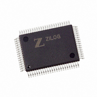
Z16C3220FSG Zilog, Z16C3220FSG Datasheet - Page 23

Z16C3220FSG
Manufacturer Part Number
Z16C3220FSG
Description
IC 20MHZ CMOS IUSC 80-QFP
Manufacturer
Zilog
Series
IUSC™r
Specifications of Z16C3220FSG
Controller Type
USC Controller
Interface
DMA
Voltage - Supply
4.5 V ~ 5.5 V
Current - Supply
7mA
Operating Temperature
0°C ~ 70°C
Mounting Type
Surface Mount
Package / Case
80-BQFP
Lead Free Status / RoHS Status
Lead free / RoHS Compliant
Available stocks
Company
Part Number
Manufacturer
Quantity
Price
REGISTER DESCRIPTION
This section describes the function of the various bits in the
registers of the device. Throughout this section the follow-
ing conventions are discussed:
Control bits are written and read by the CPU and are not
modified by the device. Command bits are written by the
CPU to initiate an action in the device and are read as
zeros. Status bits are controlled by the device and are read
to check device status. Any writes to status bits are ignored
by the device. Command/Status bits are controlled by both
the device and the CPU. They may be written and read by
the CPU and may also be modified by the device.
23
Z
ILOG
Address: 00000 (Shared)
D15 D14 D13 D12 D11 D10 D9
0
0
0
0
0
0
0
0
1
1
1
1
1
1
1
1
Notes:
*
**
(Shared) means, shared between DMA Channels
(WO) means Write Only
0
0
0
0
1
1
1
1
0
0
0
0
1
1
1
1
0
0
1
1
0
0
1
1
0
0
1
1
0
0
1
1
0
1
0
1
0
1
0
1
0
1
0
1
0
1
0
1
Null Command
Reset This Channel
Start This Channel
Start/Continue This Channel
Pause This Channel
Abort This Channel
Reserved
Start/Init This Channel
Reset Highest IUS
Reset All Channels
Start All Channels
Start/Continue All Channels
Pause All Channels
Abort All Channels
Reserved
Start/Init All Channels
0
0
0
0
1
1
1
1
*
0
0
1
1
0
0
1
1
Figure 8. DMA Command/Address Register
0
1
0
1
0
1
0
1
D8
Tx Channel
Rx Channel
Reserved
Reserved
Reserved
Reserved
Reserved
Reserved
D7
P R E L I M I N A R Y
D6
D5
Channel Select (WO)
Channel Command
D4
D3
Reserved bits are not used in this implementation of the
device and may or may not be physically present in the
device. Any reserved bits that are physically present are
readable and writable, but reserved bits that are not
present are always read as zeros. To ensure compatibility
with future versions of the device, reserved bits should
always be written with zeros. Reserved commands should
not be used for the same reason.
First, the DMA registers unique to the IUSC are described
in the following pages (Figures 8-17) and then the serial
channel registers are described (Figures 18-81).
D2
D1
**
D0
Upper//Lower Byte Select (WO)
Address 0 (WO)
Address 1 (WO)
Address 2 (WO)
Address 3 (WO)
Address 4 (WO)
Byte//Word Access (WO)
Pointer Channel Select (WO)
Master Bus Request Enable
PS97USC0200
Z16C32 IUSC
™


