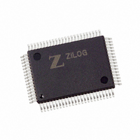
Z16C3220FSC Zilog, Z16C3220FSC Datasheet - Page 17

Z16C3220FSC
Manufacturer Part Number
Z16C3220FSC
Description
IC 20MHZ CMOS IUSC 80-QFP
Manufacturer
Zilog
Series
IUSC™r
Specifications of Z16C3220FSC
Controller Type
USC Controller
Interface
DMA
Voltage - Supply
4.5 V ~ 5.5 V
Current - Supply
7mA
Operating Temperature
0°C ~ 70°C
Mounting Type
Surface Mount
Package / Case
80-BQFP
Lead Free Status / RoHS Status
Contains lead / RoHS non-compliant
Available stocks
Company
Part Number
Manufacturer
Quantity
Price
Company:
Part Number:
Z16C3220FSC
Manufacturer:
ZILOG
Quantity:
210
Company:
Part Number:
Z16C3220FSC
Manufacturer:
ZILOG
Quantity:
885
DATA COMMUNICATIONS CAPABILITIES (Continued)
Character Counters
The IUSC contains separate 16-bit character counters for
the receiver and transmitter. The receive character counter
is set to a programmable starting value or automatically at
the beginning of each received frame and can be reloaded
under software control during a frame. The counter decre-
ments with each receive character. At the end of the
receive message the current value in the counter is auto-
matically loaded into a four-deep FIFO. With the Receive
Status Block (RSB) feature enabled, the counter value and
the status (RCSR) can be automatically transferred to
memory following the data. In array and linked list modes,
the RSB can be transferred to the array or list entry for easy
software access. This allows DMA transfer of data to
proceed without CPU intervention at the end of a received
frame, as the values in the FIFO allow the CPU to determine
the status and length of each frame.
Similarly, the transmit character counter is loaded auto-
matically at the beginning of each transmit frame and can
be reloaded under software control during a frame. The
counter is decremented with each write to the transmit
FIFO. When the counter reaches zero, and that byte is sent,
the transmitter automatically terminates the message in
the appropriate fashion (usually by sending the CRC and
the closing flag or sync character) without requiring CPU
intervention. In linked list and array modes, the transmit
character count and frame control word can be fetched
from the linked list or array.
Baud Rate Generators
The IUSC contains two Baud Rate Generators. Each gen-
erator consists of a 16-bit time constant register and a 16-
bit down counter. In operation, the counter decrements
with each cycle of its selected input clock, and the time
constant can be automatically reloaded when the count
reaches zero. The output of the Baud Rate Generator
toggles when the counter reaches a count of one-half of the
time constant and again when the counter reaches zero. A
new time constant can be written at any time but the new
value does not take effect until the next load of the counter.
The outputs of both baud rate generators are sent to the
clock multiplexer for use internally or externally. The input
17
Z
ILOG
P R E L I M I N A R Y
to the Baud Rate Generator can be the /TxC pin, the /RxC
pin, a PORT pin, or the output of either counter. The baud
rate generator output frequency is related to the baud rate
generator input clock frequency by the following formula:
Output frequency = Input frequency/time constant + 1.
Note: This allows an output frequency in the range of 1 to
The output of either Baud Rate Generator can be used as
the transmit or receive clock, the reference clock input to
the DPLL circuit, and/or can be output on the /RxC or /TxC
pin.
Digital Phase-Locked Loop
The IUSC contains a DPLL (Digital Phase-Locked Loop) to
recover clock information from a data stream with NRZI or
Biphase encoding. The DPLL is driven by a clock that is
nominally 8, 16 or 32 times the receive data rate. The DPLL
uses this clock, along with the data stream, to construct a
clock for the data. This clock can be routed to the receiver,
transmitter, or both, or to a pin for use externally. In all
modes, the DPLL counts the input clock to create nominal
bit times. While counting, the DPLL watches the incoming
data stream for transitions. When a transition is detected,
the DPLL may make a count adjustment (during the next
counting cycle) to produce an output clock which tracks
the incoming bit cells. The DPLL provides properly phased
transmit and receive clocks to the clock multiplexer.
Counters
The IUSC contains two 5-bit counters, which are pro-
grammed to divide an input clock by 4, 8, 16 or 32. The
outputs of these two counters are sent to the clock multi-
plexer. The counters can be used as prescalers for the
Baud Rate Generators. They also provide a stable transmit
clock from a common source when the DPLL is providing
the receive clock. The PORT0 and PORT1 pins can be
used as inputs to the counters.
1/65536 of the input frequency, inclusive.
PS97USC0200
Z16C32 IUSC
™


