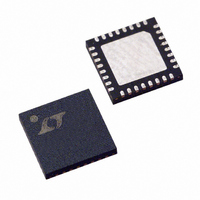
LTC1955EUH#TR Linear Technology, LTC1955EUH#TR Datasheet - Page 12

LTC1955EUH#TR
Manufacturer Part Number
LTC1955EUH#TR
Description
IC SMART CARD INTERFC DUAL 32QFN
Manufacturer
Linear Technology
Datasheet
1.LTC1955EUHPBF.pdf
(20 pages)
Specifications of LTC1955EUH#TR
Controller Type
Smart Card Interface
Interface
4-Wire Serial
Voltage - Supply
1.7 V ~ 5.5 V
Current - Supply
10µA
Operating Temperature
-40°C ~ 85°C
Mounting Type
Surface Mount
Package / Case
32-QFN
Lead Free Status / RoHS Status
Contains lead / RoHS non-compliant
Available stocks
Company
Part Number
Manufacturer
Quantity
Price
LTC1955
OPERATION
Smart Card Detection Circuits
The PRES A/PRES B pins are used to detect the presence
of a smart card. An automatic debounce circuit waits until
a smart card has been present for a continuous period
of typically 35ms. Once a valid card indication exists,
the status bit for that channel is updated and may be
polled by cycling data through the serial port. The D
pin (equivalent to D15) of the serial port can be used to
indicate the presence of a card on channel A in real time
if LD is held low.
The PRES A/PRES B pins have built-in pull-up current
sources, so no external components are required for
switch detection. The pull-up current sources are designed
to have a small current when the pin voltage is below ap-
proximately 1V, but somewhat higher current when the
pin voltage reaches 1V. This helps maintain low power
dissipation when a card is present and yet fast response
time to a card removal.
The PRES A/PRES B pins can be confi gured to respond
to either normally open or normally closed switches via
the NC/NO pin.
Activation/Deactivation
For maximum fl exibility, the activation sequencing of the
smart card is left to the application programmer. Upon
activation, to comply with relevant smart card standards,
none of the smart card signal pins will be allowed to go
high before the smart card supply voltage (V
reached its fi nal value. Deactivation can be achieved either
manually or automatically. An electrical fault condition will
trigger the automatic deactivation.
Manual deactivation may be performed under software
control by setting the smart card pins to 0V in the desired
sequence via the control pins (SYNC, ASYNC, R
and the serial port). For most applications, this will be
cumbersome and the built-in deactivation will be used
instead.
12
CCA
/V
IN
CCB
, DATA
) has
OUT
Automatic Deactivation
The built-in deactivation sequence can be executed via the
serial port simply by setting the appropriate control bits
(D0 and D1 or D8 and D9) to 0. The deactivation sequence
is outlined below.
1. The RST A/RST B pin for that channel is immediately
2. The deactivation of the CLK A/CLK B pins depends upon
3. The I/O A/I/O B, C4A and C8A pins for that channel are
4. The V
If an error occurs on one smart card, operation of the
other card is unaffected.
Electrical Fault Detection
Several types of faults are detected by the LTC1955. They
include V
CLK A/CLK B, RST A/RST B, C8A, C4A short-circuit, card
removal during a transaction, failed answer to reset (ATR),
supply undervoltage or UNDERV and chip overtemperature.
To prevent false errors from plaguing the microcontroller,
the electrical faults are acted upon only after a 5μs (min)
timeout period. Card removal during transaction faults
initiate the deactivation sequence immediately.
brought low.
which type of card is used:
If the smart card was set to asynchronous mode, then
the CLK A/CLK B pin will be latched low on its next
falling edge. If no falling edges occur within 5μs (min),
then the CLK A/CLK B line is forced low.
If the smart card was set to synchronous mode, then the
CLK A/CLK B pin is immediately latched at its current
value (either high or low) and then forced low after a
duration of 5μs (min). During the 5μs timeout period,
changes on SYNC will be ignored.
brought low.
CCA
CCA
/V
/V
CCB
CCB
pin is brought low.
undervoltage, V
CCA
/V
CCB
overcurrent,
1955fb


