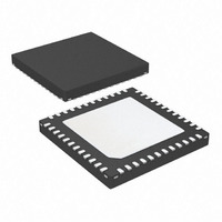
AT83C26-ZTUL Atmel, AT83C26-ZTUL Datasheet - Page 21

AT83C26-ZTUL
Manufacturer Part Number
AT83C26-ZTUL
Description
IC SMART CARD READER 1/PM 48-QFN
Manufacturer
Atmel
Datasheet
1.AT83C26-ALTUL.pdf
(77 pages)
Specifications of AT83C26-ZTUL
Controller Type
Smart Card Reader Interface
Interface
2-Wire
Voltage - Supply
3 V ~ 5.5 V
Current - Supply
65mA
Operating Temperature
-40°C ~ 85°C
Mounting Type
Surface Mount
Package / Case
48-VQFN Exposed Pad, 48-HVQFN, 48-SQFN, 48-DHVQFN
For Use With
AT89STK-09 - EVAL BOARD FOR AT83C26
Lead Free Status / RoHS Status
Lead free / RoHS Compliant
- Current page: 21 of 77
- Download datasheet (706Kb)
DC/DC B converter
7511D–SCR–02/07
Figure 9. DC/DC A Converter Initialization Procedure
The DC/DC B converter is controlled by DCDCB register.
The DC/DC B converter can be switched on even if CPRES2 pin remains inactive.
A write operation in VDCB[1:0] (0x01, 0x02, 0x03) starts the DC/DC. When the output voltage
remains within the voltage range specified by VDCB_OK[1:0], the VDCB_OK bit is set.
The DC/DC B Converter can work in two different modes which are selected by STEPREGB:
•
•
The current drawn from power supply by the DC/DC B converter is controlled during the startup
phase in order to avoid high transient current mainly in Pump Mode which could cause the
power supply voltage to drop dramatically. This control is done by means of bits DEM-
BOOSTB[1:0], which increases progressively the startup current level.
Pump Mode (STEPREGB = 0): an external inductance of 10 µH must be connected
between pins LIB and VCC. VCC can be higher or lower than selected voltage.
Regulator mode (STEPREGB = 1): no external inductance is required but VCC must be
always higher than selected voltage+0.3V.
DEMBOOSTA[1:0]
Increment
DEMBOOSTA[1:0]=[0:0]
Set Time-out to 3 ms
DC/DC A Converter
Initialization Failure
DEMBOOSTA[1:0]
is at Maximum?
VCARD_OK1=1
Time-out
Expired
END
DEMBOOSTA[1:0]
current overflow
to adjust the
Decrement
END
AT83C26
21
Related parts for AT83C26-ZTUL
Image
Part Number
Description
Manufacturer
Datasheet
Request
R

Part Number:
Description:
SMART CARD READER INTERFACE WITH POWER MANAGEMENT
Manufacturer:
ATMEL [ATMEL Corporation]
Datasheet:

Part Number:
Description:
IC SMART CARD READER 1/PM 48VQFP
Manufacturer:
Atmel
Datasheet:

Part Number:
Description:
IC SMART CARD READER 1/PM 48VQFP
Manufacturer:
Atmel
Datasheet:

Part Number:
Description:
IC SMART CARD READER 3/5V 48VQFP
Manufacturer:
Atmel
Datasheet:

Part Number:
Description:
IC SMART CARD READER 1/PM 48-MLF
Manufacturer:
Atmel
Datasheet:

Part Number:
Description:
RFID Modules & Development Tools 3V Smart card reader
Manufacturer:
Atmel
Datasheet:

Part Number:
Description:
Multiple Smart Card Reader Interface With Power Management
Manufacturer:
ATMEL Corporation
Datasheet:

Part Number:
Description:
DEV KIT FOR AVR/AVR32
Manufacturer:
Atmel
Datasheet:

Part Number:
Description:
INTERVAL AND WIPE/WASH WIPER CONTROL IC WITH DELAY
Manufacturer:
ATMEL Corporation
Datasheet:

Part Number:
Description:
Low-Voltage Voice-Switched IC for Hands-Free Operation
Manufacturer:
ATMEL Corporation
Datasheet:

Part Number:
Description:
MONOLITHIC INTEGRATED FEATUREPHONE CIRCUIT
Manufacturer:
ATMEL Corporation
Datasheet:

Part Number:
Description:
AM-FM Receiver IC U4255BM-M
Manufacturer:
ATMEL Corporation
Datasheet:

Part Number:
Description:
Monolithic Integrated Feature Phone Circuit
Manufacturer:
ATMEL Corporation
Datasheet:

Part Number:
Description:
Multistandard Video-IF and Quasi Parallel Sound Processing
Manufacturer:
ATMEL Corporation
Datasheet:


