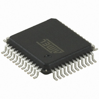
AT83C26-ALTUL Atmel, AT83C26-ALTUL Datasheet - Page 28

AT83C26-ALTUL
Manufacturer Part Number
AT83C26-ALTUL
Description
IC SMART CARD READER 1/PM 48VQFP
Manufacturer
Atmel
Datasheet
1.AT83C26-ALTUL.pdf
(77 pages)
Specifications of AT83C26-ALTUL
Controller Type
Smart Card Reader Interface
Interface
2-Wire
Voltage - Supply
3 V ~ 5.5 V
Current - Supply
65mA
Operating Temperature
-40°C ~ 85°C
Mounting Type
Surface Mount
Package / Case
48-TQFP, 48-VQFP
For Use With
AT89STK-09 - EVAL BOARD FOR AT83C26
Lead Free Status / RoHS Status
Lead free / RoHS Compliant
Available stocks
Company
Part Number
Manufacturer
Quantity
Price
Emergency deactivation sequence on SCn interface (n=1, 2, 3, 4, 5)
28
AT83C26
•
•
It is a self-timed sequence which cannot be interrupted when started (see Figure 17). Each step
is separated by a delay based on Td equal to 8 periods of DCCLK, typically 2 to 2.4 µs:
Notes:
The card emergency automatic deactivation is triggered when one the following condition
occurs:
•
•
If the power supply is disconnected, a standard deactivation is started when VCC = VPFDP.
When VCC is equal to VPFDM, the emergency deactivation occurs and eventually ends the
standard deactivation.
Figure 17. Deactivation Sequence
Reset pin going low (SC1, SC2, SC3, SC4, SC5)
Power Fail (VPFDP)
1. T0: CARDRSTn is cleared, SHUTDOWNA (for SC1) bit is set.
2. T0 + 5 x Td:CARDCKn is cleared, CKSTOPn, CARDIOn and IODIS are set.
3. T0 + 6 x Td: CARDIOn is cleared.
4. T0 + 7 x Td: VCARDn[1:0] = 00.
Software TWI Reset (SC1, SC2, SC3, SC4, SC5)
Power fail on VCC (SC1, SC2, SC3, SC4, SC5)
1. Setting ICARDERR1 by software does not trigger a deactivation on SC1. VCARDERRn can
2. If CCLKn=A2 or A2/2, deactivation follows fig13 with 2 timing modifications: t1=5.5*Td and
3. Td is based on DCCLK clock.
be used to deactivate the card by software.
t2=0.5*Td.
CRST
CCLK
CVCC
CIO,
CC4,
CC8
5 x Td
t1
Td
t2
Td
7511D–SCR–02/07


