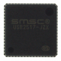
USB2517-JZX SMSC, USB2517-JZX Datasheet - Page 30

USB2517-JZX
Manufacturer Part Number
USB2517-JZX
Description
IC USB 2.0 7PORT HUB CTLR 64QFN
Manufacturer
SMSC
Datasheet
1.USB2512B-AEZG.pdf
(76 pages)
Specifications of USB2517-JZX
Controller Type
USB 2.0 Controller
Interface
Serial EEPROM
Voltage - Supply
3 V ~ 3.6 V
Current - Supply
130mA
Operating Temperature
0°C ~ 70°C
Mounting Type
Surface Mount
Package / Case
64-QFN
Lead Free Status / RoHS Status
Lead free / RoHS Compliant
Other names
638-1081
Available stocks
Company
Part Number
Manufacturer
Quantity
Price
Company:
Part Number:
USB2517-JZX
Manufacturer:
Standard
Quantity:
2 937
Part Number:
USB2517-JZX
Manufacturer:
SMSC
Quantity:
20 000
USB 2.0 Hi-Speed Hub Controller
Datasheet
Figure 6.1
shows a simple example of how this LED circuit will be implemented. The circuit should be
replicated for each of the x LED pins on the SMSC hub. In this circuit, when the LED pin is driven to
a logic low state, the Green LED will light up. When the LED pin is driven to a Logic High state the
Red LED will light up. When a 1 KHz square wave is driven out on the LED pin, the Green and Red
LED's will both alternately light up giving the effect of the color Orange. When nothing is driven out on
the LED pin (i.e. the pin floats to a "tri-state" condition), neither the Green nor Red LED will light up,
this is the "Off" state.
The assignment is as follows:
LED_A_N[x:1] = LED D[x:1] (Downstream Port [x:1])
The usage is as follows:
LED_A_N[x] Driven to Logic Low = LS device attached (Green LED)
LED_A_N[x] Driven to Logic High = FS device attached (Red LED)
LED_A_N[x] Pulsed @ 1 KHz = HS device attached (Orange color by pulsing Red & Green).
LED_A_N[x] is tri-state= No devices are attached, or the hub is in suspend, LED's are off.
Revision 1.1 (04-26-10)
30
SMSC USB251x
DATASHEET


