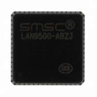
LAN9500-ABZJ SMSC, LAN9500-ABZJ Datasheet - Page 10

LAN9500-ABZJ
Manufacturer Part Number
LAN9500-ABZJ
Description
IC USB 2.0 ETHER CTRLR 56-QFN
Manufacturer
SMSC
Type
Single Chip MAC and PHY Controllerr
Specifications of LAN9500-ABZJ
Controller Type
USB 2.0 Controller
Interface
MII
Voltage - Supply
3 V ~ 3.6 V
Current - Supply
78mA
Operating Temperature
0°C ~ 70°C
Mounting Type
Surface Mount
Package / Case
56-QFN
Product
Ethernet Controllers
Number Of Transceivers
1
Standard Supported
IEEE 802.3 or IEEE 802.3u
Data Rate
10 Mbps or 100 Mbps
Supply Voltage (max)
3.6 V
Supply Voltage (min)
0 V
Supply Current (max)
97.5 mA, 135.2 mA
Maximum Operating Temperature
+ 70 C
Ethernet Connection Type
10BASE-T or 100BASE-TX
Maximum Power Dissipation
0.6657 W (Typ)
Minimum Operating Temperature
0 C
Mounting Style
SMD/SMT
Lead Free Status / RoHS Status
Lead free / RoHS Compliant
Other names
638-1071
Available stocks
Company
Part Number
Manufacturer
Quantity
Price
Company:
Part Number:
LAN9500-ABZJ
Manufacturer:
SMSC
Quantity:
591
Part Number:
LAN9500-ABZJ
Manufacturer:
SMSC
Quantity:
20 000
Revision 1.1 (06-25-08)
4.2
4.2.1
JUMPER
JP1
JP2
JP3
JP4
JP5
JP6
JP7
LAN9500 CEB with MII Interface
The LAN9500 CEB with MII interface provides the same functionality as the LAN9500 CEB (non-MII)
with additional features. The LAN9500 CEB with MII interface provides a user accessible MII interface
for connection to an external PHY and a JTAG debugging interface. The provided jumpers allow for
additional configuration of the device, including the option to set the device to bus-powered or self-
powered mode.
LAN9500 CEB with MII Interface - Jumper Settings
Table 4.1
MII interface. A dashed line “---” shown in the “Position” column indicates the board’s default jumper
setting. These settings may be changed as needed. However, any deviation from the default settings
must be approached with care and knowledge of the board. An incorrect jumper setting may disable
the board.
Note 4.1
Note 4.2
DESCRIPTION
SMSC Test Jumper
JTAG Connect Jumper
PHY Control Jumper
(Note
+5V MII Connect Jumper
Power Supply Control Jumper
(Note
3.3V Reg. Connect Jumper
(Note
VBUS_DET Connect Jumper
4.1)
4.2)
4.2)
details the various jumper settings available on the LAN9500 customer evaluation board with
When an external PHY is connected to the MII port of the LAN9500, the LAN9500 CEB
must be configured for external PHY operation.
JP5 and JP7 must always be connected in the same positions (i.e. 1-2 and 1-2, or 2-3 and
2-3 only).
Table 4.1 LAN9500 CEB with MII Interface Jumper Settings
PRODUCT INTRODUCTION
POSITION
1
1
2------3
1
1------2
2
1------2
1------2
2
1
2
2
2
2
3
3
10
SETTINGS
This jumper must always be left unconnected.
IN: Bus switch connects JTAG header to MII/JTAG pins
OUT: Bus switch disconnects JTAG header from MII/JTAG
pins
Enables external PHY
Enables internal PHY
IN: Connects +5V to MII connector
OUT: Disconnects +5V from MII connector
Device is bus powered via USB cable (JP4 must be removed)
Device is external +5V supply powered
IN: 3.3V regulator connected to 3.3V plane
OUT: 3.3V regulator disconnected from 3.3V plane
VBUS_DET connected to +3.3V (use when bus powered)
VBUS_DET connected to resistor divider and capacitor circuit.
(provides filtering, voltage divider and bleed path for
VBUS_DET when USB cable is disconnected)
Hi-Speed USB 2.0 to 10/100 Ethernet Controller
LAN9500/LAN9500i Product Introduction
SMSC LAN9500/LAN9500i


