USB2512AI-AEZG SMSC, USB2512AI-AEZG Datasheet - Page 55
USB2512AI-AEZG
Manufacturer Part Number
USB2512AI-AEZG
Description
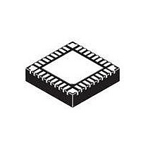
IC CTRLR USB2.0 2PORT 36QFN
Manufacturer
SMSC
Type
USB HUB Controllerr
Specifications of USB2512AI-AEZG
Controller Type
USB 2.0 Controller
Interface
Serial EEPROM
Voltage - Supply
3 V ~ 3.6 V
Current - Supply
95mA
Operating Temperature
-40°C ~ 85°C
Mounting Type
Surface Mount
Package / Case
36-QFN
Operating Supply Voltage
3.3 V
Maximum Operating Temperature
+ 85 C
Minimum Operating Temperature
- 40 C
Mounting Style
SMD/SMT
Operating Temperature Range
- 40 C to + 85 C
Supply Current
90 mA
For Use With
638-1041 - BOARD EVAL FOR USB2512/USB2512I
Lead Free Status / Rohs Status
Lead free / RoHS Compliant
Other names
638-1089
Available stocks
Company
Part Number
Manufacturer
Quantity
Price
Company:

Part Number:
USB2512AI-AEZG
Manufacturer:
Standard
Quantity:
2 736
Company:
Part Number:
USB2512AI-AEZG
Manufacturer:
SMSC
Quantity:
4 450
Part Number:
USB2512AI-AEZG
Manufacturer:
SMSC
Quantity:
20 000


USB 2.0 Hi-Speed Hub Controller
Datasheet
SMSC USB251x
8.3.9
8.3.9.1
8.3.9.2
8.4
8.5
8.6
8.6.1
Normal
Internal Pull-Down
LED
Number
Part
SMBus Alert Response Address
The SMBALERT# signal is not supported by the hub.
Undefined Registers
The registers shown in
return 00h. Writes to undefined registers have no effect and do not return an error.
Reserved Registers
Reserved registers should be written to ‘0’ unless otherwise specified. Contents read should be
ignored.
To configure the SMSC hub in its default configuration, strap CFG_SEL[2:0] to 00h. This procedure
configures the hub to the internal defaults and enables the strapping options. Please see
"Internal Register Set (Common to EEPROM and SMBus)"
pin strapping options, please see
default values. Options include port disable and non-removable pin strapping.
The USB251x can be configured via a combination of internal default values and pin strap options.
Please see
The strapping option pins only cover a limited sub-set of the configuration options. The internal default
values will be used for the bits & registers that are not controlled by a strapping option pin. Please
refer to
Non-Removable Strap Option
The strap function of the NON_REM[x:0] pins are enabled through the internal default configuration.
The driver type of each strap pin is I/O (no internal pull-up or pull-down for the input function). Use
this type of strap option for NON_REM[1:0].
Low. Use the Strap High configuration to set the strap option value to a ‘1’. Use the Strap Low
configuration to set the strap option value to ‘0’.
Default Configuration Option
Default Strapping Options
Strap Options
Table 8.2
USB251x
USB251xi
USB251xA
USB251xAi
Table 8.2
for the internal default values that are loaded when this option is selected.
for specific details on how to enable the default/pin-strap configuration option.
Table 8.2
Table 8.7 Summary of Strap Options
USB251xB
USB251xBi
are the defined registers in the hub. Reads to undefined registers
Chapter 5, Pin Descriptions
DATASHEET
55
Resistor Value
47 - 100 kΩ
47 - 100 kΩ
Figure 8.3
10 kΩ
(R)
shows an example of Strap High and Strap
for the list of the default values. For specific
Only applicable to port power pins.
Contains a built-in resistor.
for instructions on how to modify the
Notes
Revision 1.1 (04-26-10)
Section 8.2.1,
Related parts for USB2512AI-AEZG
Image
Part Number
Description
Manufacturer
Datasheet
Request
R

Part Number:
Description:
Manufacturer:
Standard Microsystems (SMSC)
Datasheet:

Part Number:
Description:
FAST ETHERNET PHYSICAL LAYER DEVICE
Manufacturer:
SMSC Corporation
Datasheet:
Part Number:
Description:
357-036-542-201 CARDEDGE 36POS DL .156 BLK LOPRO
Manufacturer:
SMSC Corporation
Datasheet:
Part Number:
Description:
357-036-542-201 CARDEDGE 36POS DL .156 BLK LOPRO
Manufacturer:
SMSC Corporation
Datasheet:
Part Number:
Description:
357-036-542-201 CARDEDGE 36POS DL .156 BLK LOPRO
Manufacturer:
SMSC Corporation
Datasheet:
Part Number:
Description:
4-PORT USB2.0 HUB CONTROLLER
Manufacturer:
SMSC Corporation
Datasheet:
Part Number:
Description:
Manufacturer:
SMSC Corporation
Datasheet:
Part Number:
Description:
Manufacturer:
SMSC Corporation
Datasheet:
Part Number:
Description:
FDC37C672ENHANCED SUPER I/O CONTROLLER WITH FAST IR
Manufacturer:
SMSC Corporation
Datasheet:
Part Number:
Description:
COM90C66LJPARCNET Controller/Transceiver with AT Interface and On-Chip RAM
Manufacturer:
SMSC Corporation
Datasheet:
Part Number:
Description:
Manufacturer:
SMSC Corporation
Datasheet:
Part Number:
Description:
Manufacturer:
SMSC Corporation
Datasheet:
Part Number:
Description:
Manufacturer:
SMSC Corporation
Datasheet:
Part Number:
Description:
Manufacturer:
SMSC Corporation
Datasheet: