CS82C59A Intersil, CS82C59A Datasheet - Page 9
CS82C59A
Manufacturer Part Number
CS82C59A
Description
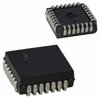
IC INTERRUPTER CMOS 8MHZ 28-PLCC
Manufacturer
Intersil
Datasheet
1.CS82C59AZ.pdf
(22 pages)
Specifications of CS82C59A
Controller Type
CMOS Priority Interrupt Controller
Interface
System Bus
Voltage - Supply
4.5 V ~ 5.5 V
Current - Supply
1mA
Operating Temperature
0°C ~ 70°C
Mounting Type
Surface Mount
Package / Case
28-PLCC
Lead Free Status / RoHS Status
Contains lead / RoHS non-compliant
Available stocks
Company
Part Number
Manufacturer
Quantity
Price
Company:

Part Number:
CS82C59A
Manufacturer:
HARRIS
Quantity:
5 510
Part Number:
CS82C59A
Manufacturer:
HARRIS
Quantity:
20 000
Company:
Part Number:
CS82C59A-10
Manufacturer:
HARRIS
Quantity:
5 510
Company:
Part Number:
CS82C59A-10
Manufacturer:
LT
Quantity:
5 510
Company:
Part Number:
CS82C59A-12
Manufacturer:
HARRIS
Quantity:
111
Company:
Part Number:
CS82C59A-12Z
Manufacturer:
Intersil
Quantity:
872
Part Number:
CS82C59A-12Z
Manufacturer:
INTERSIL
Quantity:
20 000


e. If lC4 = 0, then all functions selected in lCW4 are set to
NOTE: Master/Slave in ICW4 is only used in the buffered mode.
Initialization Command Words 1 and 2 (ICW1, lCW2)
A5 - A15: Page starting address of service routines. In an
8080/85 system the 8 request levels will generate CALLS to
8 locations equally spaced in memory. These can be
programmed to be spaced at intervals of 4 or 8 memory
locations, thus, the 8 routines will occupy a page of 32 or 64
bytes, respectively.
The address format is 2 bytes long (A0 - A15). When the
routine interval is 4, A0 - A4 are automatically inserted by the
82C59A, while A5 - A15 are programmed externally. When
the routine interval is 8, A0 - A5 are automatically inserted by
the 82C59A while A6 - A15 are programmed externally.
The 8-byte interval will maintain compatibility with current
software, while the 4-byte interval is best for a compact jump
table.
In an 80C86/88/286 system, A15 - A11 are inserted in the
five most significant bits of the vectoring byte and the
82C59A sets the three least significant bits according to the
interrupt level. A10 - A5 are ignored and ADI (Address
interval) has no effect.
zero. (Non-Buffered mode (see note), no Auto-EOI,
8080/85 system).
FIGURE 6. 82C59A INITIALIZATION SEQUENCE
NO (SNGL = 1)
NO (IC4 = 0)
INTERRUPT REQUESTS
READY TO ACCEPT
9
CASCADE
NEEDED
IS ICW4
MODE
ICW1
ICW2
ICW3
ICW4
IN
YES (SNGL = 0))
YES (IC4 = 1)
82C59A
82C59A
LTlM:
ADI:
SNGL: Single. Means that this is the only 82C59A in the
IC4:
Initialization Command Word 3 (ICW3)
This word is read only when there is more than one 82C59A
in the system and cascading is used, in which case
SNGL = 0. It will load the 8-bit slave register. The functions of
this register are:
a. In the master mode (either when SP = 1, or in buffered
b. In the slave mode (either when SP = 0, or if BUF = 1 and
NOTE: (The slave address must correspond to the IR line it is
connected to in the master ID).
Initialization Command Word 4 (ICW4)
SFNM: If SFNM = 1, the special fully nested mode is pro-
BUF:
M/S:
AEOI: If AEOI = 1, the automatic end of interrupt mode is
µPM:
mode when M/S = 1 in lCW4) a “1” is set for each slave in
the bit corresponding to the appropriate IR line for the
slave. The master then will release byte 1 of the call
sequence (for 8080/85 system) and will enable the corre-
sponding slave to release bytes 2 and 3 (for 80C86/88/
286, only byte 2) through the cascade lines.
M/S = 0 in lCW4), bits 2 - 0 identify the slave. The slave
compares its cascade input with these bits and if they are
equal, bytes 2 and 3 of the call sequence (or just byte 2 for
80C86/88/286) are released by it on the Data Bus.
If LTlM = 1, then the 82C59A will operate in the level
ALL address interval. ADI = 1 then interval = 4; ADI
If this bit is set - lCW4 has to be issued. If lCW4 is
If BUF = 1, the buffered mode is programmed. In
If buffered mode is selected: M/S = 1 means the
Microprocessor mode: µPM = 0 sets the 82C59A for
interrupt mode. Edge detect logic on the interrupt
inputs will be disabled.
= 0 then interval = 8.
system. If SNGL = 1, no ICW3 will be issued.
not needed, set lC4 = 0.
grammed.
buffered mode, SP/EN becomes an enable output
and the master/slave determination is by M/S.
82C59A is programmed to be a master, M/S = 0
means the 82C59A is programmed to be a slave. If
BUF = 0, M/S has no function.
programmed.
8080/85 system operation, µPM = 1 sets the
82C59A for 80C86/88/286 system operation.
March 17, 2006
FN2784.5
Related parts for CS82C59A
Image
Part Number
Description
Manufacturer
Datasheet
Request
R

Part Number:
Description:
Intersil Corporation [CMOS Serial Controller Interface]
Manufacturer:
Intersil Corporation
Datasheet:
Part Number:
Description:
Manufacturer:
Intersil Corporation
Datasheet:
Part Number:
Description:
357-036-542-201 CARDEDGE 36POS DL .156 BLK LOPRO
Manufacturer:
Intersil Corporation
Datasheet:
Part Number:
Description:
1024-Word x 4-Bit LSI Static RAM
Manufacturer:
Intersil Corporation
Datasheet:
Part Number:
Description:
General Purpose NPN Transistor Arrays FN341.4
Manufacturer:
Intersil Corporation
Datasheet:
Part Number:
Description:
CMOS 16-Bit Microprocessor
Manufacturer:
Intersil Corporation
Datasheet:
Part Number:
Description:
Manufacturer:
Intersil Corporation
Datasheet:
Part Number:
Description:
Manufacturer:
Intersil Corporation
Datasheet:
Part Number:
Description:
Manufacturer:
Intersil Corporation
Datasheet:
Part Number:
Description:
Manufacturer:
Intersil Corporation
Datasheet:
Part Number:
Description:
CMOS 6-Bit Latch and Decoder Memory Interfaces
Manufacturer:
Intersil Corporation
Datasheet:
Part Number:
Description:
CA3046General Purpose NPN Transistor Arrays
Manufacturer:
Intersil Corporation
Datasheet:
Part Number:
Description:
Manufacturer:
Intersil Corporation
Datasheet:
Part Number:
Description:
TR909 DLC/FLC SLIC with Low Power Standby
Manufacturer:
Intersil Corporation
Datasheet:
Part Number:
Description:
Manufacturer:
Intersil Corporation
Datasheet: