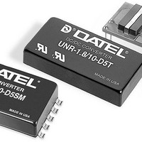
UNR-2.5/15-D5 Murata Power Solutions Inc, UNR-2.5/15-D5 Datasheet - Page 4

UNR-2.5/15-D5
Manufacturer Part Number
UNR-2.5/15-D5
Description
DC/DC Converters & Regulators 37.5W 5V to 2.5V 15A
Manufacturer
Murata Power Solutions Inc
Series
UNRr
Datasheet
1.UNR-2.515-D5.pdf
(8 pages)
Specifications of UNR-2.5/15-D5
Product
Non-Isolated / POL
Output Power
38 W
Input Voltage Range
4.75 V to 5.5 V
Input Voltage (nominal)
5 V
Number Of Outputs
1
Output Voltage (channel 1)
2.5 V
Output Current (channel 1)
15 A
Lead Free Status / Rohs Status
Lead free / RoHS Compliant
www.murata-ps.com
Output ripple/noise (also referred to as periodic and random deviations or
PARD) can be reduced below specified limits using filtering techniques, the
simplest of which is the installation of additional external output capacitors.
Output capacitors function as true filter elements and should be selected for
bulk capacitance, low ESR, and appropriate frequency response. Any scope
measurements of PARD should be made directly at the DC/DC output pins
with scope probe ground less than 0.5" in length.
All external capacitors should have appropriate voltage ratings and be
located as close to the converters as possible. Temperature variations for all
relevant parameters should be taken into consideration.
The most effective combination of external I/O capacitors will be a function
of your line voltage and source impedance, as well as your particular load
and layout conditions. Our Applications Engineers can recommend potential
solutions and discuss the possibility of our modifying a given device’s internal
filtering to meet your specific requirements. Contact our Applications Engi-
neering Group for additional details.
Input Fusing
UNR 30-66W Series DC/DC converters are not internally fused. Certain
applications and or safety agencies may require the installation of fuses at
the inputs of power conversion components. Fuses should also be used if the
possibility of sustained, non-current-limited, input-voltage polarity reversals
exist. To allow for inrush transients, fuses should rated for approximately 2
times the maximum input rms current.
Input Overvoltage and Reverse-Polarity Protection
UNR 30-66W Series DC/DC converters do not incorporate either input over-
voltage or input reverse-polarity protection. Input voltages in excess of the
listed absolute maximum ratings and input polarity reversals of longer than
"instantaneous" duration can cause permanent damage to these devices.
On/Off Control
The On/Off Control pin may be used for remote on/off operation. UNR 30-
66W Series DC/DC converters are designed so that they are enabled when
the control pin is pulled high or left open, and disabled when the control pin
is pulled low (see Performance Specifications for limits). As shown in Figure
2, all models have internal 5k pull-up resistors to +Input.
Dynamic control of the on/off function is best accomplished with a mechani-
cal relay or open-collector/open-drain drive circuit (optically isolated if appro-
priate). The drive circuit should be able to sink appropriate current when
activated and withstand appropriate voltage when deactivated.
Applying an external voltage to the On/Off Control pin when no input power
is applied to the converter can cause permanent damage to the converter.
The on/off control function, however, is designed such that the converter
can be disabled (control pin pulled low) while input power (system 5V
power) is ramping up and then "released" once the input has stabilized.
The time duration between the point at which the converter is released and
its fully loaded output settles to within specified accuracy can be found in
the Performance/Functional Specifications Table. See Start-Up Time for more
details.
Start-Up Time
The V
ramping input voltage crosses the lower limit of the specified input voltage
range (4.75 Volts) and the fully loaded output voltage enters and remains
within it specified accuracy band. Actual measured times will vary with input
source impedance, external input capacitance, and the slew rate and final
value of the input voltage as it appears to the converter.
The On/Off to V
the Remote On/Off Control with the nominal input voltage already applied to
the converter. The specification defines the interval between the time at which
the converter is turned on and the fully loaded output voltage enters and
remains within its specified accuracy band. See Typical Performance Curves
for details
Output Overvoltage Protection
UNR 30-66W Series DC/DC converters do not incorporate output overvolt-
age protection. In the extremely rare situation in which the device’s feedback
loop is broken, the output voltage may run to excessively high levels (V
V
all possible overvoltage situations, voltage limiting circuitry must be provided
external to the power converter.
Output Overcurrent Detection
Overloading the output of a power converter for an extended period of
time will invariably cause internal component temperatures to exceed their
maximum ratings and eventually lead to component failure. High-current-
carrying components such as inductors, FET's and diodes are at the highest
risk. UNR 30-66W Series DC/DC converters incorporate an output overcur-
rent detection and shutdown function that serves to protect both the power
converter and its load.
IN
). If it is absolutely imperative that you protect your load against any and
IN
to V
OUT
UNR Open-Frame Series
Start-Up Time is the interval between the time at which a
OUT
Start-Up Time assumes the converter is turned off via
Technical enquiries email: sales@murata-ps.com, tel:
Single Output, Non-Isolated, 15-20 Amp
Figure 2. Driving the On/Off Control Pin
5V
IN,
7
6
8
1.5-3.3V
+INPUT
ON/OFF
CONTROL
INPUT
RETURN
5k
OUT
DC/DC Converters
UNR30-66W.B01 Page 4 of 8
+1 508 339 3000
OUT
=


