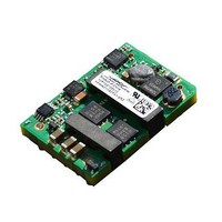
KNW015A0F41Z Lineage Power, KNW015A0F41Z Datasheet

KNW015A0F41Z
Specifications of KNW015A0F41Z
Related parts for KNW015A0F41Z
KNW015A0F41Z Summary of contents
Page 1
Data Sheet February 28, 2011 36 –75Vdc Input; 3.3V Output; 15A Output Current RoHS Compliant Applications Distributed power architectures Wireless networks Access and optical networking equipment including Power over Ethernet (PoE) Enterprise networks Latest generation ...
Page 2
February 28, 2011 Absolute Maximum Ratings Stresses in excess of the absolute maximum ratings can cause permanent damage to the device. These are absolute stress ratings only, functional operation of the device is not implied at these or any other ...
Page 3
February 28, 2011 Electrical Specifications (continued) Parameter Output Voltage Set-point ( =25°C) IN IN, min O O, max A Output Voltage (Over all operating input voltage, resistive load, and temperature conditions until end of ...
Page 4
February 28, 2011 General Specifications Parameter Calculated Reliability Based upon Telcordia SR- 332 Issue 2: Method Case 3, (I =80 =40°C, Airflow = 200 lfm), 90% confidence A Powered Random Vibration ( IN, ...
Page 5
Data Sheet February 28, 2011 Characteristic Curves The following figures provide typical characteristics for the KNW015A0F (3.3V, 15A identical for either positive or negative remote On/Off logic. OUTPUT CURRENT, I Figure 1. Converter Efficiency versus Output Current. TIME, ...
Page 6
Data Sheet February 28, 2011 Test Configurations TO OSCILLOSCOPE L TEST 12μH C 220μF S 33μF E.S.R.<0.1 @ 20°C 100kHz NOTE: Measure input reflected ripple current with a simulated source inductance ( 12μH. Capacitor C TEST possible battery ...
Page 7
Data Sheet February 28, 2011 Feature Description Remote On/Off Two remote on/off options are available. Positive logic turns the module on during a logic high voltage on the ON/OFF pin, and off during a logic low. Negative logic remote On/Off, ...
Page 8
Data Sheet February 28, 2011 Feature Descriptions (continued) auto-restart option (4), it will remain in the hiccup mode as long as the overcurrent condition exists; it operates normally, once the output current is brought back into its specified range. The ...
Page 9
... EMC Considerations The KNW015A0F series module shall also meet limits of EN55022 Class A with a recommended single stage filter, shown in Figure 14. Please contact your Lineage Power Sales Representative for further information. Figure 14. Single stage filter used for test results. LINEAGE POWER KNW015A0F Series Power Modules: 36 – ...
Page 10
Data Sheet February 28, 2011 Surface Mount Information Pick and Place The KNW015A0F modules use an open frame construction and are designed for a fully automated assembly process. The pick and place locations on the module are the larger magnetic ...
Page 11
... For guidance on appropriate soldering, cleaning and drying procedures, refer to Lineage Power Board Mounted Power Modules: Soldering and Cleaning Application Note (AN04-001). LINEAGE ...
Page 12
Data Sheet February 28, 2011 Mechanical Outline for Surface Mount Module Dimensions are in millimeters and [inches]. Tolerances: x.x mm 0.5 mm [x.xx in. 0.02 in.] (unless otherwise indicated) x.xx mm 0.25 mm [x.xxx in 0.010 ...
Page 13
Data Sheet February 28, 2011 Mechanical Outline for Through-Hole Module Dimensions are in millimeters and [inches]. Tolerances: x.x mm 0.5 mm [x.xx in. 0.02 in.] (unless otherwise indicated) x.xx mm 0.25 mm [x.xxx in 0.010 in.] ...
Page 14
Data Sheet February 28, 2011 Recommended Pad Layout Dimensions are in and millimeters [inches]. Tolerances: x.x mm 0.5 mm [x.xx in. 0.02 in.] (unless otherwise indicated) x.xx mm 0.25 mm [x.xxx in 0.010 in.] SMT Recommended ...
Page 15
Data Sheet February 28, 2011 Packaging Details The Sixteenth-brick SMT versions are supplied in tape & reel as standard. Details of tape dimensions are shown below. Modules are shipped in quantities of 140 modules per reel. Tape Dimensions Dimensions are ...
Page 16
... Ordering Information Please contact your Lineage Power Sales Representative for pricing, availability and optional features. Table 1. Device Code Product Codes Input Voltage KNW015A0F41-SRZ 48V (36-75Vdc) KNW015A0F41Z 48V (36-75Vdc) Table 2. Device Coding Scheme and Options Character and Position Characteristic Form Factor K Family Designator ...


