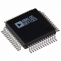
AD1835AAS-REEL Analog Devices Inc, AD1835AAS-REEL Datasheet - Page 20

AD1835AAS-REEL
Manufacturer Part Number
AD1835AAS-REEL
Description
IC CODEC 2ADC/8DAC 24 BIT 52MQFP
Manufacturer
Analog Devices Inc
Type
Stereo Audior
Specifications of AD1835AAS-REEL
Rohs Status
RoHS non-compliant
Data Interface
Serial
Resolution (bits)
24 b
Number Of Adcs / Dacs
2 / 8
Sigma Delta
Yes
S/n Ratio, Adcs / Dacs (db) Typ
105 / 108
Dynamic Range, Adcs / Dacs (db) Typ
105 / 108
Voltage - Supply, Analog
4.5 V ~ 5.5 V
Voltage - Supply, Digital
4.5 V ~ 5.5 V
Operating Temperature
-40°C ~ 85°C
Mounting Type
Surface Mount
Package / Case
52-BQFP
Single Supply Voltage (typ)
3.3/5V
Single Supply Voltage (min)
3/4.5V
Single Supply Voltage (max)
5.5V
Package Type
MQFP
For Use With
EVAL-AD1835AEB - BOARD EVALUATION FOR AD1835A
Lead Free Status / RoHS Status
Not Compliant
AD1835A
Address
15, 14, 13, 12
1100
Address
15, 14, 13, 12
1101
Address
15, 14, 13, 12 11
1110
Address
15, 14, 13, 12
0010 = DACL1
0011 = DACR1
0100 = DACL2
0101 = DACR2
0110 = DACL3
0111 = DACR3
1000 = DACL4
1001 = DACR4
Table VIII. DAC Volume Control
R/W
RES RES Reserved Clocking Scaling Peak Readback
0
R/W
RES
11
0
R/W
11
0
R/W
11
0
10
0
RES
10
0
9
0, 0
RES
10
0
RES
10
0
Master/Slave ADC
Aux Mode
9
0 = Slave
1 = Master
Function
DAC Volume
9, 8, 7, 6, 5, 4, 3, 2, 1, 0
0000000000 = Mute
0000000001 = 1/1023
0000000010 = 2/1023
1111111110 = 1022/1023
1111111111 = 1023/1023
IMCLK
8, 7, 6
00 = MCLK
01 = MCLK
10 = MCLK
11 = MCLK
RES
9
0
Data Format
8, 7, 6
000 = I
001 = RJ
010 = DSP
011 = LJ
100 = Packed 256
101 = Packed 128
110 = Auxiliary 256
111 = Auxiliary 512
Table XII. ADC Control 3
Table XI. ADC Control 2
Table X. ADC Control 1
2
2/3
2
2
S
ADC
5
0 = Disabled Peak Readback 000 = Normal Mode 00 = Normal Mode
1 = Enabled Peak Readback All others reserved
Filter
8
0 = All Pass
1 = High-Pass
–20–
Address
15, 14, 13, 12
1010 = Left ADC 1
1011 = Right ADC
ADC Data-
Function
Word Width
5, 4
00 = 24 Bits
01 = 20 Bits
10 = 16 Bits
11 = Reserved
Function
ADC
Power-Down
7
0 = Normal
1 = Power-Down
Function
R/W RES Six Data Bits
11
Test Mode
DAC
4, 3, 2
Table IX. ADC Peak
3, 2
0, 0
Reserved
10
0
Function
9, 8, 7, 6, 5, 4
000000 = 0.0 dBFS 0000
000001 = –1.0 dBFS
000010 = –2.0 dBFS These four
111111 = –63.0 dBFS bits are
Sample
Rate
6
0 = 48 kHz
1 = 96 kHz
ADC MUTE
Right
1
0 = On
1 = Mute
ADC
Test Mode
1, 0
All others reserved
Reserved
5, 4, 3, 2, 1, 0
0, 0, 0, 0, 0, 0
0, 0, 0, 0, 0, 0
Four Fixed
Bits
3, 2, 1, 0
always zero.
Left
0
0 = On
1 = Mute
REV. A


