MAXFILTERBRD+ Maxim Integrated Products, MAXFILTERBRD+ Datasheet - Page 3
MAXFILTERBRD+
Manufacturer Part Number
MAXFILTERBRD+
Description
BOARD EVAL MAX7408/7415/418-7425
Manufacturer
Maxim Integrated Products
Datasheet
1.MAXFILTERBRD.pdf
(5 pages)
Specifications of MAXFILTERBRD+
Main Purpose
Filters, Lowpass, Switched-Capacitor Filters
Embedded
No
Utilized Ic / Part
MAX7408-MAX7415, MAX7418-MAX7425
Primary Attributes
Bare PCB for Lowpass, Switched-Capacitor Filters
Technology Type
Filter Evaluation Kit
Lead Free Status / RoHS Status
Lead free / RoHS Compliant
For Use With/related Products
MAX74x


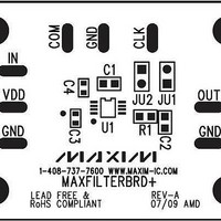
The MAXFILTERBRD is an unpopulated PCB design to
evaluate the MAX7408–MAX7415/MAX7418–MAX7425
5th-order, lowpass SCFs.
The MAXFILTERBRD uses the internal oscillator when
a capacitor is installed on C1. Refer to corresponding
installed IC data sheet.
For the MAX7409/MAX7410/MAX7413/MAX7414, the
frequency can be altered using the following formula:
where k = 30 x 10
frequency.
For the MAX7408/MAX7411/MAX7412/MAX7415, k = 27 x 10
For the MAX7418/MAX7421/MAX7422/MAX7425, k = 87 x 10
For the MAX7419/MAX7420/MAX7423/MAX7424, k = 110 x 10
Detailed Description of Hardware
f
OSC
_______________________________________________________________________________________
3
and f
(kHz) = k/C1 (pF)
OSC
is the internal oscillator
Internal Clock
3
3
3
.
.
.
An external clock that matches the specification of the
corresponding IC data sheet can be used by cutting
the trace of jumper JU2. Drive the CLK pin with a CMOS
gate powered from 0 to VDD. Apply the clock signal to
the CLK pad.
The MAXFILTERBRD is configured for normal operation
once the desired IC is installed. The desired IC enters
shutdown by cutting the trace of jumper JU1 and driving
the IC SHDN pin low through the side of the jumper that
is still connected to the part.
MAXFILTERBRD
External Clock
Shutdown
3
Related parts for MAXFILTERBRD+
Image
Part Number
Description
Manufacturer
Datasheet
Request
R

Part Number:
Description:
MAX7528KCWPMaxim Integrated Products [CMOS Dual 8-Bit Buffered Multiplying DACs]
Manufacturer:
Maxim Integrated Products
Datasheet:
Part Number:
Description:
Single +5V, fully integrated, 1.25Gbps laser diode driver.
Manufacturer:
Maxim Integrated Products
Datasheet:
Part Number:
Description:
Single +5V, fully integrated, 155Mbps laser diode driver.
Manufacturer:
Maxim Integrated Products
Datasheet:
Part Number:
Description:
VRD11/VRD10, K8 Rev F 2/3/4-Phase PWM Controllers with Integrated Dual MOSFET Drivers
Manufacturer:
Maxim Integrated Products
Datasheet:
Part Number:
Description:
Highly Integrated Level 2 SMBus Battery Chargers
Manufacturer:
Maxim Integrated Products
Datasheet:
Part Number:
Description:
Current Monitor and Accumulator with Integrated Sense Resistor; ; Temperature Range: -40°C to +85°C
Manufacturer:
Maxim Integrated Products
Part Number:
Description:
TSSOP 14/A�/RS-485 Transceivers with Integrated 100O/120O Termination Resis
Manufacturer:
Maxim Integrated Products
Part Number:
Description:
TSSOP 14/A�/RS-485 Transceivers with Integrated 100O/120O Termination Resis
Manufacturer:
Maxim Integrated Products
Part Number:
Description:
QFN 16/A�/AC-DC and DC-DC Peak-Current-Mode Converters with Integrated Step
Manufacturer:
Maxim Integrated Products
Part Number:
Description:
TDFN/A/65V, 1A, 600KHZ, SYNCHRONOUS STEP-DOWN REGULATOR WITH INTEGRATED SWI
Manufacturer:
Maxim Integrated Products
Part Number:
Description:
Integrated Temperature Controller f
Manufacturer:
Maxim Integrated Products
Part Number:
Description:
SOT23-6/I�/45MHz to 650MHz, Integrated IF VCOs with Differential Output
Manufacturer:
Maxim Integrated Products
Part Number:
Description:
SOT23-6/I�/45MHz to 650MHz, Integrated IF VCOs with Differential Output
Manufacturer:
Maxim Integrated Products
Part Number:
Description:
EVALUATION KIT/2.4GHZ TO 2.5GHZ 802.11G/B RF TRANSCEIVER WITH INTEGRATED PA
Manufacturer:
Maxim Integrated Products
Part Number:
Description:
QFN/E/DUAL PCIE/SATA HIGH SPEED SWITCH WITH INTEGRATED BIAS RESISTOR
Manufacturer:
Maxim Integrated Products
Datasheet: