E2K-X15MF2 5M Omron, E2K-X15MF2 5M Datasheet - Page 8
E2K-X15MF2 5M
Manufacturer Part Number
E2K-X15MF2 5M
Description
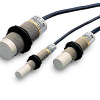
Proximity Sensors E2K-X15MF2 W/ 5 MET ER CABLE
Manufacturer
Omron
Series
E2K-Xr
Type
Proximity Sensorr
Datasheet
1.E2K-X4MF1.pdf
(9 pages)
Specifications of E2K-X15MF2 5M
Maximum Operating Temperature
70 C
Supply Voltage
12 VDC to 24 VDC
Supply Current
15 mA
Output Voltage
1 V
Operating Supply Voltage
10 VDC to 30 VDC
Mounting Style
Panel
Sensing Distance
15 mm
Minimum Operating Temperature
- 25 C
Current Rating
200 mA
Features
Permits non-contact detection of metallic and non-metallic objects
Voltage Rating
24 VDC
Lead Free Status / Rohs Status
Lead free / RoHS Compliant


E2K-X
When mounting the proximity sensor in or near a metallic panel, be sure to provide a minimum distance as shown in the tables below. This
prevents the sensor from being affected by metallic objects other than the target.
When Mounting Directly to Metal Panel or Object
When Using Optional Mounting Brackets
To prevent mutual interference between two sensors, be sure to space the two sensors at a distance greater than that shown in the table
below.
DC Switching Sensors
In applying any of the E2K-X ME series proximity sensors as a
voltage output type, note that an unwanted output may be pro-
duced momentarily (50 ms max.) when power is applied with a
target moving toward the E2K-X ME1(F1) or with a target
moving away from the E2K-X ME2(F2). After the power appli-
cation, a minimum of 50 ms is required before the sensor circuit
can operate. Move the target toward or away from the proximity
sensor after this time period.
If a high voltage or power line runs near the proximity sensor
cable, be sure to wire the sensor cable through a metal conduit to
protect the sensor from malfunctioning or damage.
The proximity sensor is provided with a surge suppressor circuit.
However, if any large surge generation source (i.e. motor, weld-
ing machine, etc.) exists in the vicinity of the proximity sensor,
insert a surge suppressor (such as a varistor) into the surge
generating source.
Drawing
dimension
d (dia.)
D
m
n
Drawing
dimension
G
H
Drawing
dimension
A
B
EFFECTS OF SURROUNDING METAL
REQUIRED WARM-UP TIME BEFORE OPERATION
USING METAL CONDUIT
SURGE PROTECTION
MUTUAL INTERFERENCE
Sensor model
E2K-X4M
20 mm (0.79 in)
50 mm (1.97 in)
20 mm (0.79 in)
60 mm (2.36 in)
Sensor model
E2K-X4M
20 mm (0.79 in)
30 mm (1.18 in)
Sensor model
E2K-X4M
80 mm (3.15 in)
70 mm (2.76 in)
8 mm (0.32 in)
E2K-X8M
20 mm (0.79 in)
50 mm (1.97 in)
20 mm (0.79 in)
12 mm (0.47 in)
60 mm (2.36 in)
E2K-X8M
20 mm (0.79 in)
30 mm (1.18 in)
E2K-X8M
150 mm (5.91 in)
110 mm (4.33 in)
9
E2K-X15M
10 mm (0.39 in)
50 mm (1.97 in)
10 mm (0.39 in)
25 mm (0.98 in)
60 mm (2.36 in)
E2K-X15M
10 mm (0.39 in)
30 mm (1.18 in)
E2K-X15M
300 mm (11.81 in)
200 mm (7.87 in)
AC Switching Sensors
After applying power to a proximity sensor, a minimum of 100 ms
is required before the sensor circuit reaches its steady state. The
load is in the OFF state during this period. Do not move the target
toward or away from the proximity sensor until the sensor circuit
enters the steady state. The operation indicator (LED) will
illuminate momentarily when the power is turned ON or OFF, but
the output stage circuit is in a normal operating state.
To ground
H
A
G
D
ød
Metal
B
E2K-X
n
m
Related parts for E2K-X15MF2 5M
Image
Part Number
Description
Manufacturer
Datasheet
Request
R

Part Number:
Description:
Proximity Sensors E2K-X4ME2 W/ 5 METER CABLE
Manufacturer:
Omron
Datasheet:
Part Number:
Description:
Proximity Sensors E2K-X8MY1 W/ 5 METER CABLE
Manufacturer:
Omron
Datasheet:
Part Number:
Description:
Proximity Sensors E2K-X8ME1 W/ 10 METE R CABLE
Manufacturer:
Omron
Datasheet:
Part Number:
Description:
Proximity Sensors E2K-X4ME1 W/ 5 METER CABLE
Manufacturer:
Omron
Datasheet:
Part Number:
Description:
Proximity Sensors E2K-X4MY1 W/ 5 METER CABLE
Manufacturer:
Omron
Datasheet:
Part Number:
Description:
Proximity Sensors Cap M18 8 mm AC2W-NO
Manufacturer:
Omron
Datasheet:
Part Number:
Description:
Proximity Sensors CAP PROX M30 15mm NPN-NO
Manufacturer:
Omron
Datasheet:
Part Number:
Description:
Proximity Sensors Cap M30 15 mm PNP-NO
Manufacturer:
Omron
Datasheet:
Part Number:
Description:
Proximity Sensors Cap M18 8 mm PNP-NO
Manufacturer:
Omron
Datasheet:
Part Number:
Description:
CAP PROX M12, 4mm PNP-NC
Manufacturer:
Omron
Datasheet:
Part Number:
Description:
CAP PROX M12, 4mm PNP-NC
Manufacturer:
Omron
Datasheet:

Part Number:
Description:
G6S-2GLow Signal Relay
Manufacturer:
Omron Corporation
Datasheet:
Part Number:
Description:
Compact, Low-cost, SSR Switching 5 to 20 A
Manufacturer:
Omron Corporation
Datasheet:
Part Number:
Description:
Manufacturer:
Omron Corporation
Datasheet: