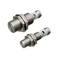
E2FM-X2B1-M1 Omron, E2FM-X2B1-M1 Datasheet - Page 9

E2FM-X2B1-M1
Manufacturer Part Number
E2FM-X2B1-M1
Description
Proximity Sensors PNP M12 body M12 DC3 wire
Manufacturer
Omron
Series
E2FMr
Datasheet
1.E2FM-X5B1-M1.pdf
(12 pages)
Specifications of E2FM-X2B1-M1
Maximum Operating Temperature
+ 70 C
Supply Voltage
10 V to 30 V
Mounting Style
Panel
Sensing Distance
2 mm
Minimum Operating Temperature
- 25 C
Features
NO
Sensor Type
Inductive
Sensing Object
Metallic
Response Frequency
100Hz
Material - Body
Stainless Steel
Shielding
Shielded
Voltage - Supply
10 V ~ 30 V
Output Type
PNP-NO
Terminal Type
Connector
Package / Case
Cylinder, Threaded - M8
Lead Free Status / Rohs Status
Lead free / RoHS Compliant
E2FM
Safety Precautions
This product is not designed or rated for ensuring
safety of persons. Do not use it for such purposes.
Never use this product with an AC power supply.
Otherwise, explosion may result.
The following precautions must be observed to ensure safe operation.
1. Do not use the Sensor in an environment where inflammable or
2. Do not attempt to disassemble, repair, or modify any Sensors.
3. Power Supply Voltage
4. Incorrect Wiring
5. Connection without a Load
Do not use the Sensor under ambient conditions that exceed the
ratings.
1. Do not use the Sensor in the following locations.
2. The Sensor may malfunction if used near ultrasonic cleaning
3. Laying the Sensor wiring in the same conduit or duct as high-
4. Cleaning
● Design
Influence of Surrounding Metal
When the Proximity Sensor is embedded in metal, make sure that the
clearances given in the following table are maintained. The values
depend on the type of nuts used for mounting. Be sure to use the
supplied nuts (SUS303).
explosive gas is present.
Do not use a voltage that exceeds the rated operating voltage
range. Applying a voltage that is higher than the operating voltage
range may result in explosion or fire.
Be sure that the power supply polarity and other wiring is correct.
Incorrect wiring may cause explosion or fire.
If the power supply is connected directly without a load, the internal
elements may explode or burn. Be sure to insert a load when
connecting the power supply.
equipment, high-frequency equipment, transceivers, cellular
phones, inverters, or other devices that generate a high-frequency
electric field. Refer to the Technical Guide Photoelectric Sensors
for typical measures.
voltage wires or power lines may result in incorrect operation and
damage due to induction. Wire the Sensor using a separate
conduit or independent conduit.
Never use thinner or other solvents. Otherwise, the Sensor surface
may be dissolved.
(1) Outdoor locations directly subject to sunlight, rain, snow, or
(2) Locations subject to atmospheres with chemical vapors, in
(3) Locations subject to corrosive gas
water droplets
particular solvents and acids
l
Precautions for Correct Use
Precautions for Safe Use
WARNING
D
d dia.
l
m
n
Note: The influence from other non-magnetic surrounding metals is nearly the
Mutual Interference
When installing two or more Sensors face-to-face or side-by-side,
ensure that the minimum distances given in the following table are
maintained.
Chips from Cutting Aluminum
Normally, chips from cutting aluminum or cast iron will not cause a
detection signal to be output even if it adheres to or accumulates on
the detection surface. In the following cases, however, a detection
signal may be output. Remove the cutting chips in these cases.
● Mounting
Do not tighten the nut with excessive force. A washer must be used
with the nut. Do not use tightening force that exceeds the values in the
following table.
1. If d ≥
2. If the cutting chips are pressed down
Model
E2FM-X1R5@
E2FM-X2@
E2FM-X5@
E2FM-X10@
E2FM-X1R5@
E2FM-X2@
E2FM-X5@
E2FM-X10@
Model
E2FM-X1R5@
E2FM-X2@
E2FM-X5@
E2FM-X10@
Model
E2FM-X1R5@
E2FM-X2@
E2FM-X5@
E2FM-X10@
surface where d is the cutting chip size
and D is the detection surface size
same as that from aluminum.
Model
2
3
D at the center of the detection
Item
Dimension
Embedding
Aluminum
Aluminum
Aluminum
Aluminum
material
110
Iron
Iron
Iron
Iron
35
40
65
(Unit: mm)
A
(mm)
180 N·m
Torque
30 N·m
70 N·m
9 N·m
Item
100
30
35
60
B
10
16
28
16
24
10
16
D
6
0
0
0
0
l
120
18
80
30
50
12
70
d
8
Pressed down
16
24
10
16
D
0
0
0
0
d
D
B
A
Cutting chip
Detection surface
Cutting chips
4.5
4.5
20
20
40
40
m
(Unit: mm)
8
8
100
120
60
80
30
50
40
70
n
9


