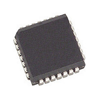
PALCE22V10-15JC Cypress Semiconductor Corp, PALCE22V10-15JC Datasheet - Page 6

PALCE22V10-15JC
Manufacturer Part Number
PALCE22V10-15JC
Description
IC SPLD 10MACROCELL 15NS 28-PLCC
Manufacturer
Cypress Semiconductor Corp
Specifications of PALCE22V10-15JC
Programmable Type
PAL FLASH
Number Of Macrocells
10
Voltage - Input
5V
Speed
15ns
Mounting Type
Surface Mount
Package / Case
28-PLCC
Family Name
Pal®
Process Technology
EECMOS
# Macrocells
10
# I/os (max)
10
Frequency (max)
83.3MHz
Propagation Delay Time
15ns
Operating Supply Voltage (typ)
5V
Operating Supply Voltage (min)
4.75V
Operating Supply Voltage (max)
5.25V
Operating Temp Range
0C to 75C
Operating Temperature Classification
Commercial
Mounting
Surface Mount
Pin Count
28
Supply Current
110mA
Lead Free Status / RoHS Status
Contains lead / RoHS non-compliant
Other names
428-1280
Available stocks
Company
Part Number
Manufacturer
Quantity
Price
Company:
Part Number:
PALCE22V10-15JC
Manufacturer:
AMD
Quantity:
5 510
Company:
Part Number:
PALCE22V10-15JC
Manufacturer:
DALLAS
Quantity:
5 510
Company:
Part Number:
PALCE22V10-15JC/4
Manufacturer:
AMD
Quantity:
12 388
]
Commercial Switching Characteristics PALCE22V10
Document #: 38-03027 Rev. **
t
t
t
t
t
t
t
t
t
t
f
f
f
t
t
t
t
t
t
Notes:
Parameter
10. This parameter is measured as the time after output disable input that the previous output data state remains stable on the output. This delay is measured to
11. This specification indicates the guaranteed maximum frequency at which a state machine configuration with external feedback can operate.
12. This specification indicates the guaranteed maximum frequency at which the device can operate in data path mode.
13. This specification indicates the guaranteed maximum frequency at which a state machine configuration with internal only feedback can operate.
14. This parameter is calculated from the clock period at f
15. The registers in the PALCE22V10 have been designed with the capability to reset during system power-up. Following power-up, all registers will be reset to a
PD
EA
ER
CO
S1
S2
H
P
WH
WL
MAX1
MAX2
MAX3
CF
AW
AR
AP
SPR
PR
7.
8.
9.
Part (a) of AC Test Loads and Waveforms is used for all parameters except t
Loads and Waveforms is used for t
Min. times are tested initially and after any design or process changes that may affect these parameters.
The test load of part (a) of AC Test Loads and Waveforms is used for measuring t
t
the point at which a previous HIGH level has fallen to 0.5 volts below V
Test Loads and Waveforms for enable and disable test waveforms and measurement reference levels.
logic LOW state. The output state will depend on the polarity of the output buffer. This feature is useful in establishing state machine initialization. To insure
proper operation, the rise in V
EA(+)
only. Please see part (e) of AC Test Loads and Waveforms for enable and disable test waveforms and measurement reference levels.
Input to Output
Propagation Delay
Input to Output
Enable Delay
Input to Output
Disable Delay
Clock to Output Delay
Input or Feedback Set-Up Time
Synchronous Preset Set-Up
Time
Input Hold Time
External Clock Period (t
Clock Width HIGH
Clock Width LOW
External Maximum
Frequency (1/(t
Data Path Maximum Frequency
(1/(t
Internal Feedback Maximum
Frequency (1/(t
Register Clock to
Feedback Input
Asynchronous Reset Width
Asynchronous Reset
Recovery Time
Asynchronous Reset to
Registered Output Delay
Synchronous Preset
Recovery Time
Power-Up Reset Time
WH
+ t
WL
Description
))
[9]
[6, 12]
CC
[10]
EA(+)
CO
CF
[6,14]
must be monotonic and the timing constraints depicted in Power-Up Reset Waveform must be satisfied
[6]
+ t
[6]
+ t
.
[8]
S
S
))
))
[8]
[6,15]
[6,13]
[11]
CO
+ t
S
)
MAX
Min.
143
200
181
2.5
2.5
internal (1/f
22V10-5
3
2
3
4
0
7
8
4
4
1
Max.
2.5
7.5
5
6
6
4
MAX3
OH
) as measured (see Note above) minus t
min. or a previous LOW level has risen to 0.5 volts above V
Min.
ER
100
166
133
10
22V10-7
3
2
5
6
0
3
3
8
5
6
1
and t
EA(-)
[2,7]
EA(+)
. The test load of part (c) of AC Test Loads and Waveforms is used for measuring
Max.
7.5
2.5
12
8
8
5
. Part (b) of AC Test Loads and Waveforms is used for t
Min.
76.9
142
111
22V10-10
12
10
3
2
6
7
0
3
3
6
8
1
Max.
10
10
10
13
7
3
S
.
Min.
55.5
83.3
68.9
22V10-15
10
10
20
15
10
10
3
2
0
6
6
1
Max.
4.5
15
15
15
20
8
OL
PALCE22V10
max. Please see part (e) of AC
Min.
33.3
35.7
38.5
22V10-25
15
15
30
13
13
25
25
15
3
2
0
1
ER
. Part (c) of AC Test
Page 6 of 13
Max.
25
25
25
15
13
25
MHz
MHz
MHz
Unit
ns
ns
ns
ns
ns
ns
ns
ns
ns
ns
ns
ns
ns
ns
ns
s


