VVGDC00-000 Carling Technologies, VVGDC00-000 Datasheet - Page 8
VVGDC00-000
Manufacturer Part Number
VVGDC00-000
Description
Switch Hardware BLK 1 AMBER OVAL LENS
Manufacturer
Carling Technologies
Type
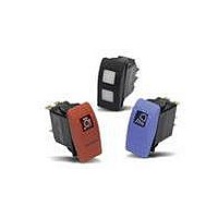
Contura Rocker Switch Actuatorr
Datasheet
1.V6D2UHHB-00000-000.pdf
(12 pages)
Specifications of VVGDC00-000
Lead Free Status / Rohs Status
Lead free / RoHS Compliant


1
Series
52
V
2 CIRCUIT
Terminal Connections as viewed
from bottom of switch:
8 terminal 10 terminal
8 - - 7
1 - - 4
2 - - 5
3 - - 6
Position:
SP
1
2
3
4
5
6
7
8
SPECIAL CIRCUITS
H*
G*
S
M*
R
E*
*Jumper between terminals 2 & 5 for circuits H, G, & M are specified in selection 4.
External jumper between terminals 2 & 4 for circuit E are provided by customer. Circuit E
may be used for SP OFF-ON-ON circuit. Circuits H, M & E not available with ratings 8 - 9.
3 RATING
1
4
5
8* 10A 250VAC, 15A 125VAC, 1/2 HP 125-250VAC, 12(2)A 250 VAC µ T85
9* 10A 250VAC, 15A 125VAC, 1/2 HP 125-250 VAC, 12(6)A 250 VAC T85
B 15A 24V
C 20A 18V
D 20A 12V
* Ratings 8 & 9 are UL, CSA, VDE, DEMKO, SEMKO, NEMKO, FIMKO & BEAB certified,
require terminations A or B for double pole circuits, & are not available with illumination cir-
cuits 4, 8, D, J, N, & T or with wire lead or solder lug terminations. Circuits 1, 4, A & D are
not available with rating 8. Ratings 8 & 9 must specify lamp code 2 (250VAC neon).
Lamp #1:above terminals 1 & 4 end of switch.; Lamp #2 above terminals 3 & 6 end of switch.
Positive (+) and negative (-) symbols apply to LED lamps only
Sealed Unsealed Lamps when Illuminated
S
A
B
C
D
E
F
G
H
U
Selections for Single Pole Switches Only:
J
K
Selections for Double Pole Switches Only:
L
M
N
P
U
8 term
1
A
J
3
C
5
E
Note: Codes J & K for circuits H, G & M. Ratings 8 & 9 require terminations A or B only.
5 ILLUMINATION & SWITCH SEALING
1 SERIES
V
4 TERMINATION/BASE STYLE
.4VA @ 28VDC Resistive
10A 250VAC 1/2 HP, 15A 125VAC 1/2 HP, No Listings
10A 250VAC 1/2 HP, 15A 125VAC 1/2 HP, UL Recognized, CSA Certified
DP
A
B
C
D
F
J
K
L
Carling
Technologies
2
Circuit
10 term
2
B
K
4
D
6
F
0
1
2
3
4
7
Z
Y
8
W
9
R
T
V
Y
5
6
4,6
10 - - 9
1 D A B
8 - - 7
1 - - 4
2 - - 5
3 - - 6
(2 & 3, 5 & 6)
(2 & 3, 5 & 6)
2 & 3, 5 & 6
2 & 3, 5 & 6
2 & 3, 5 & 6
2 & 3
5 & 6
(ON)
(ON)
ON
ON
ON
ON
ON
ON
3
Rating
1
Termination
.250 TAB (QC) no barriers
.250 TAB (QC) with barriers
.250 TAB (QC) no barriers
Solder Lug no barriers
Solder Lug
Wire Leads no barriers
Wire Leads
None
# 1
# 1
# 2
# 1
&# 2
# 1
& # 2
# 1
# 1
& # 2
# 2
# 1
& # 2
# 1
& # 2
# 1
& # 2
# 1
# 2
# 1
& # 2
# 1
& # 2
# 1
& # 2
& # 2
™
Actuator Lens position
Independent
Down
Up
Down
Down
Up
Independent
Up
Independent
Up
Independent
Independent
Independent
Down
Independent
Independent
Independent
Down
Up
Down
Down
Up
Up
Independent
Independent
Up
4
Termination
Connected Terminals
( ) - momentary
SP - single pole - uses terminals 1, 2 & 3.
DP - double pole uses terminals 1, 2, 3, 4, 5 & 6.
Terminals 7, 8, 9 & 10 for lamp circuit only.
2 & 3, 5 & 4
NONE
NONE
NONE
NONE
NONE
2 & 3
2 & 3
2 & 3
2 & 3
5 & 3
OFF
OFF
OFF
5
Illumination
2
6
Lamp
T 0 B
Jumper
No
No
Yes T2 to 5
No
No
No
No
Lamp wired to
Terminals
8+
3+
3+
3+
1+
1+
3+
8+
3+
8+
3+
8+
8+
10+ 9-
3+
6+
8+
6+
3+
3+
3+
1+
1+
3+
8+
10+ 9-
7-
7-
7-
7-
7-
7-
7-
7-
6-
7-
7-
7-
7-
8-
7-
7-
7-
6-
6-
6-
4-
4-
6-
7-
1 & 2, 4 & 5
www.carlingtech.com
7
Lamp
(OFF)
5 & 4
1 & 2
1 & 2
5 & 1
(ON)
(ON)
(ON)
OFF
OFF
OFF
OFF
ON
ON
3
8
Bracket
NOTES
Consult factory to verify horsepower rating for your particular circuit choice.
1
2
3
4
5
6
7
V-Series Contura V Sealed Rocker Switches
-
Custom colors are available. Consult factory.
White imprinting is standard on black actuators; Black imprinting is standard on white, red and
gray actuators; Custom colors are available, consult factory.
Laser Etched rocker only available with lens code Z & actuator colors black, nickel or pewter.
Additional ratings available. See page 57.
Nickel and Pewter colors only available with laser etched actuator.
Rating 9 only available with circuits 1, 4, A & D.
Consult factor for laser etched lens callout.
00
(used with codes 11-18 in selection 12) Selection 14 required when switch requires two
legends. If the two legends consist of one lens and one body legend, lens legend must
be specified in selection 12; body legend specified in selection 14.
For legend options & codes, see page 69 of this catalog
6,7 LAMP (same coding for both selections)
Selection 6: above terminals 1 & 4; Selection 7: above terminals 3 & 6
No lamp
Neon
Incandescent 4 3V
LED *
2VDC
6VDC
12VDC
24VDC
* Consult factory for “daylight bright” LED options. Typical current draw for LED is 20ma.
8 FLUSH BRACKET COLOR
No Seal
One Seal
9 ACTUATOR
No Actuator
Contura V
Contura V Laser Etch
10 LENS
Lens color for LEDs must be clear, white, or match color of LED.
Green or blue lenses are not recommended with Neon lamps.
0 - No Actuator
Clear
1
2
3
4
5
11 ACTUATOR COLOR
No Actuator 0
White
12 ACTUATOR LENS OR BODY LEGEND
13 LEGEND ORIENTATION
0
1
2
3
4
MC
MA
14 ACTUATOR LENS LEGEND
00 - No Legend this location/No actuator
11 ON
15 O O 16
For additional legend options & codes, see page 69 of this catalog.
9
Actuator
OFF
MA3MC
G R C
F N
F
No legend
Orientation 1
Orientation 2
Orientation 3
Orientation 4
No legend this location / no actuator
12 OFF
Y
4G200
10
Lens
0
1 125VAC 2 250VAC
Red
A
B
C
D
Black
B
C
White
6
7
8
9
A
4G
ON
O O 17 O I
N F
Black C
Nickel D
(used with codes 11-18 in selection 12)
F
MC
MA
13
1,3,5
11
Color
MA1MC
5 6V
Amber
L
M
N
P
White
W
Y
0
G
P
Z - No Lens
Amber
B
C
D
E
F
O
I
3
1
, PANEL SEAL
Gray
Pewter E
4G
3L
4G13L
14
18 I O
12
Legend
00
6 12V
superbright superbright
Green
F
G
H
J
Gray
G
H
Green
G
H
J
K
L
H
O
I
2, 7
Red S
-
7 18V
Red
R
S
T
V
Red
M
N
P
R
S
ORIENTATION 4
13
Legend
Orientation
ACTUATOR/LENS IN PANEL
0
ORIENTATION OF
ORIENTATION 3
ORIENTATION 1
8 24V
Blue
T
U
V
W
Y
14
Actuator
Lens Legend
Lens style
& location:
#1 / #2
00
bar
bar/bar
oval
oval/bar
oval/oval
ORIENTATION 2
Related parts for VVGDC00-000
Image
Part Number
Description
Manufacturer
Datasheet
Request
R

Part Number:
Description:
Toggle Switches CARLING TECHNOLOGIES
Manufacturer:
Carling Technologies
Datasheet:
Part Number:
Description:
CARLING POWER SWITCH LIGHTED 10 AMP 250 VOLT AC
Manufacturer:
Carling Technologies
Part Number:
Description:
CARLING SWITCH
Manufacturer:
Carling Technologies

Part Number:
Description:
SWITCH PB SPST OFF-MOM SCRW TERM
Manufacturer:
Carling Technologies
Datasheet:
Part Number:
Description:
SWITCH
Manufacturer:
Carling Technologies
Datasheet:

Part Number:
Description:
INDUCTOR PLATE FOR THERMAL BRKR
Manufacturer:
Carling Technologies

Part Number:
Description:
CIRCUIT BREAKER ROCKER 9A SP BK
Manufacturer:
Carling Technologies
Datasheet:

Part Number:
Description:
CIRCUIT BREAKER MAGNETIC 20A
Manufacturer:
Carling Technologies
Datasheet:
Part Number:
Description:
LIGHT INDICATOR GRN 12VDC PNLMNT
Manufacturer:
Carling Technologies
Part Number:
Description:
CONTURA ILL INDICATOR 12V RED
Manufacturer:
Carling Technologies
Part Number:
Description:
Current Regulator Diodes CURRENT REGULATOR DIODES 3.6mA
Manufacturer:
Carling Technologies
Part Number:
Description:
Rocker Switches
Manufacturer:
Carling Technologies
Datasheet: